Tolerance control is essential in high-precision machining to ensure components meet exact specifications. This guide provides a systematic, technical approach to achieving superior dimensional accuracy, supported by detailed parameters and practical methods.
Understanding Tolerance Control in High-Precision Machining
Tolerance control involves maintaining dimensional accuracy within specified limits during machining. In high-precision applications, tolerances can be as tight as ±0.001 mm, requiring meticulous planning and execution. The objective is to minimize deviations from nominal dimensions while ensuring repeatability across production runs.
Several factors influence tolerance control, including machine capabilities, tool selection, material properties, and process parameters. Each must be optimized to achieve the desired precision. For example, CNC lathes typically achieve tolerances of ±0.005 mm for cylindrical features, while advanced grinding machines can reach ±0.0005 mm for surface finishes.
A systematic approach involves defining tolerances based on functional requirements, selecting appropriate equipment, and implementing rigorous quality checks. Statistical process control (SPC) can monitor dimensional variations, ensuring consistency within 3σ limits for high-precision parts.
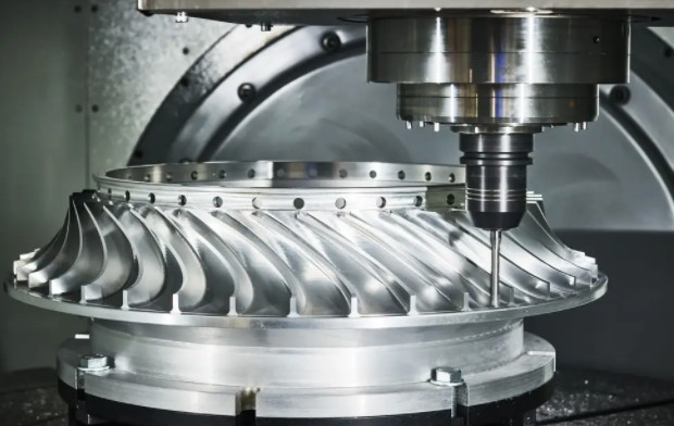
Selecting High-Precision Machining Equipment
The choice of machining equipment significantly impacts tolerance control. High-precision CNC machines, such as 5-axis milling centers or Swiss-type lathes, provide superior accuracy due to their rigidity and advanced control systems. A 5-axis CNC machine can maintain positional accuracy within ±0.002 mm across complex geometries.
Equipment maintenance is critical for consistent performance. Regular calibration of machine axes and spindles ensures accuracy. A spindle runout of less than 0.001 mm is recommended for high-precision applications. Thermal compensation systems can mitigate dimensional changes due to temperature variations, maintaining accuracy within ±0.0008 mm.
Environmental control in the machining facility also plays a role. Maintaining a temperature of 20±1°C and humidity of 40–60% minimizes thermal expansion and material distortion. Vibration isolation systems further enhance precision by reducing external disturbances.
| Machine Type | Tolerance Capability | Key Features |
|---|---|---|
| 5-Axis CNC Milling | ±0.002 mm | High rigidity, multi-axis control |
| Swiss-Type Lathe | ±0.003 mm | Sliding headstock, precision guide bush |
| Surface Grinder | ±0.0005 mm | High spindle stability, fine feed control |
Optimizing Tool Selection and Setup
Tool selection is fundamental to achieving tight tolerances. Tools must be matched to the material and machining requirements. For instance, carbide tools with a cutting edge radius of 0.005 mm are suitable for machining hardened steel, achieving surface roughness (Ra) of 0.1–0.2 µm. Diamond-coated tools are preferred for non-ferrous materials like aluminum, offering tolerances of ±0.001 mm.
Tool setup must minimize runout and vibration. Precision tool holders, such as hydraulic or shrink-fit systems, can reduce runout to below 0.003 mm. Regular tool inspection and replacement prevent wear-related inaccuracies. A tool wear limit of 0.02 mm is recommended to maintain dimensional accuracy.
Tool path optimization is also essential. Using high-speed machining (HSM) strategies with smooth, continuous tool paths reduces vibration and improves surface finish. For example, trochoidal milling with a step-over of 5–10% of tool diameter minimizes tool deflection, ensuring tolerances within ±0.002 mm.
Material Considerations for Precision Machining
Material properties significantly affect tolerance control. Materials with high machinability, such as 6061 aluminum, allow tighter tolerances (±0.002 mm) compared to challenging alloys like Inconel (±0.01 mm). Material homogeneity is critical; inclusions or voids can cause dimensional deviations.
Pre-machining treatments enhance material stability. For steel components, stress relieving at 600°C for 2 hours reduces residual stresses, improving dimensional consistency during machining. Normalizing or annealing can further ensure uniform material properties.
Consistent material sourcing is vital for repeatability. Variations in material composition or hardness between batches can lead to dimensional inaccuracies. For example, a hardness variation of ±2 HRC in tool steel can affect machining accuracy by 0.005 mm.
Optimizing Process Parameters
Process parameters, including cutting speed, feed rate, and depth of cut, must be precisely controlled. For CNC milling of stainless steel, a cutting speed of 100–150 m/min, feed rate of 0.05–0.1 mm/rev, and depth of cut of 0.2–0.5 mm can achieve tolerances of ±0.003 mm with a surface roughness (Ra) of 0.4 µm.
Adaptive control systems enhance precision by adjusting parameters in real time. Force sensors can detect excessive cutting loads, reducing feed rates to prevent tool deflection. High-pressure coolant at 70 bar minimizes thermal distortion and chip recutting, improving accuracy by 0.001 mm.
Multi-stage machining strategies also improve tolerance control. Roughing with a depth of cut of 1–2 mm removes bulk material, followed by semi-finishing and finishing with depths of 0.1–0.3 mm. This approach minimizes residual stresses and ensures dimensional accuracy within ±0.002 mm.
Implementing Quality Control Measures
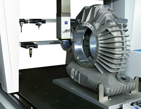
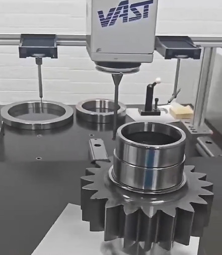
Robust quality control (QC) is essential for maintaining tolerances. In-process inspection using coordinate measuring machines (CMMs) with a resolution of 0.0001 mm verifies dimensional accuracy. Touch probes with repeatability of ±0.001 mm are ideal for complex geometries.
Statistical process control (SPC) monitors process stability. Control charts track critical dimensions, ensuring variations remain within ±3σ limits. A process capability index (Cpk) of ≥1.33 indicates reliable tolerance control for high-precision parts.
Post-machining inspection verifies final dimensions. Surface profilometers measure roughness (Ra) to ensure compliance with specifications, while optical comparators check geometric tolerances like parallelism within 0.002 mm.
Fixturing and Workholding Techniques
Effective fixturing ensures part stability during machining. Vacuum chucks or magnetic workholding systems provide uniform clamping forces, minimizing distortion. For cylindrical parts, collets with a clamping accuracy of ±0.002 mm are recommended.
Custom fixtures designed for specific part geometries reduce setup errors. For example, a fixture with locating pins of ±0.001 mm tolerance ensures repeatable part positioning. Minimizing clamping pressure to 50–100 bar prevents deformation while maintaining stability.
Modular fixturing systems allow quick setup changes, improving efficiency without compromising accuracy. Zero-point clamping systems with repeatability of ±0.005 mm are ideal for high-precision production runs.

Operator Training and Process Documentation
Skilled operators are critical for tolerance control. Training programs should cover CNC programming, tool setup, and QC techniques. Operators must understand G-code and M-code functions to optimize tool paths and parameters.
Comprehensive process documentation ensures consistency. Standard operating procedures (SOPs) detail machine settings, tool specifications, and inspection protocols. For example, an SOP might specify a spindle speed of 10,000 RPM and a feed rate of 0.08 mm/rev for aluminum machining.
Regular audits of machining processes identify deviations and ensure adherence to SOPs. Documenting process parameters and inspection results in a digital database facilitates traceability and continuous improvement.