Silicon carbide reinforced aluminum (SiC/Al) composites are widely used in high-performance applications such as satellite bearings, laser mirrors, and inertial gyroscopes due to their excellent thermal stability and high micro-yield strength. However, machining these materials presents significant difficulties due to the hard SiC particles embedded in the aluminum matrix. These particles cause tool wear, material defects like cracks, and particle pull-out during machining. This article provides a detailed, experience-based guide on overcoming these issues through material analysis, tool selection, optimized cutting parameters, and specialized thread machining techniques.
Material Characteristics and Machining Challenges
SiC/Al composites are classified as difficult-to-machine materials due to the presence of hard SiC particles, which have a hardness of 3000–3500 HV, significantly higher than the aluminum matrix. These particles act like abrasive grains in a grinding wheel, causing rapid tool wear through abrasion and impact on the cutting edge. Higher SiC content, larger particle sizes, and greater particle density exacerbate tool wear and increase the likelihood of particle dislodgement, leading to surface defects such as cracks and voids.
Traditional machining knowledge for homogeneous materials like aluminum or steel cannot be directly applied to SiC/Al composites. The unique combination of a soft matrix and hard reinforcements requires specialized approaches. Experimental cutting tests are essential to understand the material's machining behavior and to develop effective strategies.
Tool Material Selection
Tool material selection is critical for machining SiC/Al composites. Tests with YW3 cemented carbide tools on SiC/Al composites with 16–18% SiC content showed severe abrasive wear on both rake and flank faces within minutes, with tool life less than one-third that of machining carburized cast iron under identical conditions. When machining composites with 40–42% SiC, wear rates increased significantly. Coated carbide tools also failed quickly, as the hard SiC particles abraded the coating, exposing the carbide substrate and accelerating wear.
Diamond-based tools, particularly polycrystalline diamond (PCD) and chemical vapor deposition (CVD) thick-film diamond (TFD), have proven to be the most effective for machining SiC/Al composites. Diamond tools offer high hardness, excellent wear resistance, low friction coefficients, and high thermal conductivity, which reduce tool sticking and built-up edge formation. Under adequate cooling, diamond tools achieve cutting speeds of 40–120 m/min, with tool life several times longer than carbide tools and surface roughness values as low as Ra 0.8 μm.
Comparative tests on 40% SiC/Al composites using TFD, coarse-grain PCD025, and fine-grain PCD002 tools under conditions of 40 m/min cutting speed, 0.05 mm/rev feed rate, 0.5 mm depth of cut, and coolant application showed that TFD tools exhibited the lowest wear rates, followed by PCD025. Fine-grain PCD002 tools had shorter lifespans but provided better surface finishes. Coarse-grain PCD025 is suitable for rough machining where fracture toughness is critical, while TFD and single-crystal diamond tools are ideal for high-speed semi-finishing and finishing.
Tool Geometry Optimization
Tool geometry significantly affects machining performance. Increasing the rake angle reduces the main cutting force, minimizing SiC particle dislodgement, fracture, and crack formation at the material edges. A rake angle of 3°–6° is optimal for turning SiC/Al composites, balancing cutting force reduction with tool durability. Increasing the relief angle (5°–8°) facilitates easier cutting and reduces cutting forces but accelerates tool wear, requiring careful consideration.
For milling, tools with small helix angles (less than 10°) are preferred to prevent particle pull-out caused by excessive cutting forces. PCD or CVD end mills with low helix angles improve surface quality by reducing the separation of SiC particles from the aluminum matrix.
Optimized Cutting Parameters
Selecting appropriate cutting parameters is essential for achieving high surface quality and extending tool life. The following parameters have been established through extensive testing:
- Cutting Speed: Higher cutting speeds (20–40 m/min for turning, 10–40 m/min for milling) with adequate cooling improve surface finish and reduce roughness. Excessive speeds (e.g., 130 m/min) increase cutting temperature, vibration, and particle pull-out, leading to defects like pits and cracks.
- Feed Rate: Lower feed rates (0.02–0.09 mm/rev) minimize surface roughness. A feed rate of 0.09 mm/rev for turning and 0.02 mm/rev for milling produces smooth, bright surfaces.
- Depth of Cut: A depth of cut of 0.5 mm is effective for both turning and milling, as deeper cuts (e.g., 1.5 mm) increase vibration and surface defects without significantly affecting roughness.
- Coolant: Kerosene-based or TONC550-2 emulsified cutting fluids enhance tool life and surface quality by reducing cutting temperatures. Continuous coolant supply is critical to prevent tool damage from thermal shock.
The table below summarizes the recommended parameters for turning and milling SiC/Al composites:
| Process | Cutting Speed (m/min) | Feed Rate (mm/rev) | Depth of Cut (mm) | Coolant |
|---|---|---|---|---|
| Turning | 20–40 | 0.09 | 0.5 | Kerosene-based or TONC550-2 |
| Milling | 10–40 | 0.02 | 0.5 | Kerosene-based or TONC550-2 |
Thread Machining Optimization
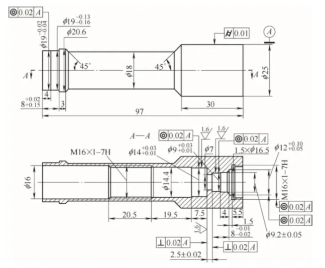
Machining internal threads (e.g., M16×1) in SiC/Al composites poses specific challenges due to the material's brittleness. During thread cutting, stress concentration at the thread entry and exit points often causes crest chipping, resulting in serrated thread profiles. This can lead to material flaking during thread engagement, compromising component safety and performance, particularly in critical applications like nozzle assemblies."
An optimized machining sequence was developed to address this issue: (1) machine the thread minor diameter, (2) chamfer the entry, (3) cut the thread, (4) machine a relief groove, and (5) chamfer the exit. Using a forming tool to create chamfers reduces stress concentration and minimizes crest chipping. Post-machining, a custom internal thread scraper (manually operated) removes burrs and smooths serrated crests at the thread entry and exit, ensuring compliance with design specifications.
Practical Implementation and Results
The strategies outlined above were applied in the batch production of inertial gyroscopes and damping plates. Diamond tools, optimized geometries (3°–6° rake angle, 5°–8° relief angle for turning; low helix angle for milling), and recommended cutting parameters (20–40 m/min speed, 0.02–0.09 mm/rev feed, 0.5 mm depth) produced smooth, bright surfaces with minimal defects. Continuous coolant application was maintained to prevent thermal damage to diamond tools, which are prone to graphitization at 700–800°C. Avoiding interruptions in cutting or changes in parameters during machining further enhanced tool life.
The optimized thread machining process eliminated crest chipping and ensured thread integrity, meeting stringent dimensional and functional requirements. Tool durability and cost-effectiveness improved significantly, enabling consistent production of high-precision components that met all technical specifications.
Conclusion
Machining SiC/Al composites requires a systematic approach that accounts for the material's unique properties. Diamond tools, particularly TFD and PCD, offer superior performance due to their hardness and wear resistance. Optimized tool geometries (3°–6° rake angle, 5°–8° relief angle for turning; low helix angle for milling) and cutting parameters (20–40 m/min speed, 0.02–0.09 mm/rev feed, 0.5 mm depth) minimize defects and improve surface quality. Specialized thread machining sequences and post-processing techniques ensure high-quality threads. Continuous coolant application and stable cutting conditions are critical to maximizing tool life. These strategies, validated through extensive testing and production, provide a reliable framework for machining SiC/Al composites in high-precision applications.