Titanium alloy grid components, characterized by ultra-deep ear holes, small-radius corners, and low rigidity, present significant machining difficulties due to their unique structural design. These components, typically used in aerospace applications, require high precision and stability during manufacturing. This article provides a systematic analysis of the machining process, detailing solutions for ear hole processing, deformation control, and small-radius corner machining. Through optimized techniques and specialized tooling, the process achieves a 100% pass rate, offering a reliable reference for similar titanium alloy components.
Structural Analysis of Grid Components
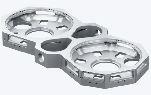
The grid component is machined from titanium alloy plates, with a final web thickness of 4 mm and rib height of 3 mm, resulting in poor structural rigidity. The component features nine non-uniformly distributed ear holes, ten U-shaped slots, and six areas designated for electrical discharge machining (EDM). Key structural characteristics include:
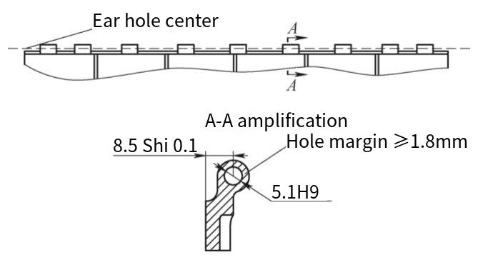
- Ear Holes: Length of 726 mm, diameter of φ5.1 mm (H9 tolerance), with an extreme length-to-diameter ratio of 142:1, posing significant machining challenges.
- Small-Radius Corners: All internal corners, including ear holes and U-shaped slots, have a radius of 2.5 mm, limiting tool selection and increasing tool breakage risks.
- EDM Areas: Post-EDM stress distribution is uneven, contributing to potential deformation.
The combination of low rigidity, high-precision requirements, and complex geometry necessitates specialized machining strategies to ensure dimensional accuracy and structural integrity.
Ear Hole Machining Process
The ear holes, with a length-to-diameter ratio of 142:1, represent the most challenging aspect of machining due to their ultra-deep, slender geometry and stringent dimensional tolerances. The primary difficulties include:
- High Dimensional Accuracy: The φ5.1 mm H9 tolerance requires precise control to avoid oversizing or undersizing, exacerbated by titanium’s tendency to contract, leading to “flared” holes.
- Lack of Precedent: No established industry methods exist for machining such ultra-deep, slender holes in titanium alloys.
- Tool Design Challenges: Drills and reamers must exceed 890 mm in length with diameters between 4.8–5.1 mm, requiring exceptional material strength and precision.
- Tooling Precision: Dedicated drill and reamer jigs require coaxiality within 0.03 mm, increasing manufacturing complexity.
To address these issues, a multi-step machining process was developed:
- Drilling φ4.8 mm Base Holes: Using specialized drill jigs, base holes are drilled from both sides of the component with 300 mm and 500 mm drills to reduce tool vibration and deflection. This approach halves the effective drill length, lowering the risk of tool breakage.
- Reaming to φ4.9 mm: A custom reamer with a φ4.5 mm front guide corrects coaxiality issues from drilling, ensuring smooth passage through misaligned holes.
- Reaming to φ5.0 mm: This step uses minimal material removal (0.1 mm) to enhance hole straightness and stability.
- Final Reaming to φ5.1 mm H9: The final reamer ensures dimensional accuracy, relying on precise tool and jig manufacturing.
The process leverages shorter tools to mitigate risks associated with ultra-long drills, achieving high precision through incremental reaming.
Tool Design and Material Specifications
The success of ear hole machining depends heavily on the precision and durability of drills and reamers. Key considerations and solutions include:
- Drill Precision: Initial drill designs exhibited straightness deviations of 3–4 mm, causing elliptical tool paths and curved holes. After regrinding and design optimization, straightness was improved to within 0.01 mm runout, ensuring straight hole profiles.
- Reamer Parameters: The final φ5.1 mm H9 reamer required precise blade diameters of 5.10–5.11 mm and a rear guide of φ5.1 mm (f6 tolerance). Initial designs with 5.105–5.115 mm blades resulted in an 88% defect rate, but iterative testing refined parameters to achieve zero defects.
- Material Selection: High-speed steel (HSS) tools showed excessive wear and insufficient strength. Switching to carbide tools significantly improved durability and reduced wear, enabling consistent machining performance.
| Tool Type | Initial Material | Final Material | Diameter (mm) | Length (mm) | Precision Requirement |
|---|---|---|---|---|---|
| Drill | HSS | Carbide | 4.8 | 300–500 | Runout ≤ 0.01 mm |
| Reamer | HSS | Carbide | 5.1 (H9) | 890 | Blade: 5.10–5.11 mm |
These refinements ensured tool reliability, enabling consistent production of high-precision ear holes.
Deformation Control Methods
The low rigidity of the grid component, combined with uneven stress distribution from EDM and machining, poses significant deformation risks. The goal was to maintain flatness within 0.3 mm. The following strategies were implemented:
- Material Stress Analysis: Titanium alloy plates (30 mm thick, hot-rolled, annealed at 750–850°C for 15–120 minutes, air-cooled) exhibit balanced tensile stress at the center and increasing stress toward surfaces. Positioning the component’s web center at the plate’s mid-thickness minimizes residual stress effects.
- Heat Treatment: Post-machining heat treatment eliminates residual stresses from rolling and machining. After EDM, flatness is measured, and additional heat treatment is applied if flatness exceeds 0.3 mm.
- Tool Path Optimization: CNC tool paths were designed to minimize stress induction, using gradual material removal to prevent distortion.
These measures collectively reduced deformation, ensuring dimensional stability across the component.
Small-Radius Corner Machining
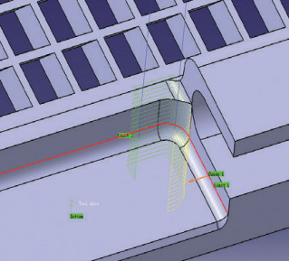
The 2.5 mm radius corners on ear holes, U-shaped slots, and external transitions require small-diameter tools (minimum 5 mm), which are prone to breakage and reduce machining efficiency. To address this, a trochoidal milling strategy was adopted using CATIA V5 software. Key features include:
- Trochoidal Milling: This technique combines tool rotation and orbital motion, allowing gradual engagement and disengagement with the material. It reduces cutting forces, minimizes heat buildup, and extends tool life.
- Cutting Parameters: Larger axial cutting depths and smaller radial widths enable full-blade engagement, improving material removal rates. The method supports high-feed, deep-cut strategies, reducing the need for multiple passes.
- Performance Benefits: Compared to conventional milling, trochoidal milling increased tool life and machining efficiency by over three times, while reducing tool breakage risks.
| Method | Tool Life (Relative) | Machining Efficiency | Tool Breakage Risk |
|---|---|---|---|
| Conventional Milling | 1x | Baseline | High |
| Trochoidal Milling | 3x | 3x Higher | Low |
This approach significantly improved the machining of small-radius corners, balancing quality and efficiency.
Implementation Results
The developed machining process was validated using two trial components and six ground-test components. Iterative refinements to tool designs, jig precision, and process parameters resulted in a 100% pass rate for ear hole machining. Flatness was consistently maintained within 0.3 mm, and small-radius corner machining efficiency improved threefold. The process not only addressed the specific requirements of the grid component but also established a robust framework for machining similar titanium alloy structures, filling an industry gap in ultra-deep hole processing.
Conclusion
The machining of titanium alloy grid components required addressing complex challenges related to ultra-deep ear holes, deformation control, and small-radius corner processing. Through a combination of specialized tooling, optimized machining strategies, and stress management techniques, the process achieved high precision and reliability. The solutions, including multi-step drilling and reaming, trochoidal milling, and stress-balanced material positioning, provide a systematic and repeatable approach for manufacturing high-quality titanium alloy components.