
This article presents an optimized machining process for inclined cylindrical bosses, utilizing macro programming and layered contour fitting. By integrating advanced tool selection, this method achieves high efficiency, high quality, and low cost in machining complex geometries. The approach addresses the limitations of traditional three-axis and five-axis machining, offering a streamlined solution for parts with stringent dimensional and surface requirements.
Introduction to Macro Programming in Machining
Macro programming leverages variable calculations and control flow statements to direct program execution, enabling concise and logical code structures. Its modular nature makes it ideal for machining complex contours with regular patterns. This article details a method that combines macro programming with optimized tool design to solve the root-clearing challenge in machining inclined cylindrical bosses. The process ensures dimensional accuracy and surface quality while minimizing production costs.
Part Structure and Machining Difficulties
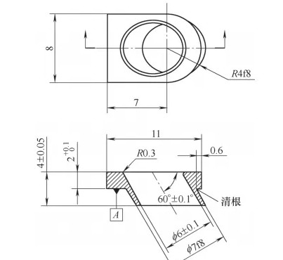
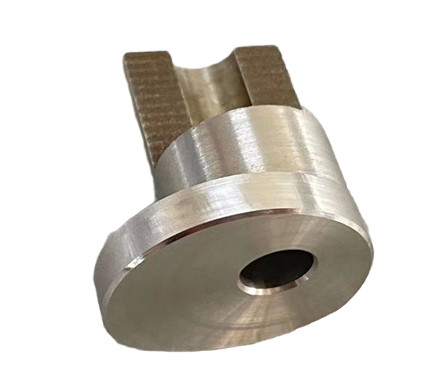
The part in question is a stainless steel component comprising a cylindrical tube intersecting a base plate at a 60° ± 0.1° angle. The base plate measures 11 mm × 8 mm × 2 mm, with the cylinder having an outer diameter of φ7 mm and an inner bore of φ(6 ± 0.1) mm. The surface roughness requirement is Ra 1.6 µm, and the root-clearance radius at the cylinder-plane intersection must be R ≤ 0.2 mm.
Traditional machining methods, whether using three-axis or five-axis CNC machines, result in residual material at the cylinder-plane intersection. In three-axis machining, the residual material is removed via electrical discharge machining (EDM) followed by manual grinding. However, EDM struggles to blend seamlessly with the machined outer diameter, and manual grinding in confined spaces leads to irregular root radii and poor roundness, yielding a qualification rate of only 60%. In five-axis machining, a small-diameter (0.4 mm) ball-end mill is used for finishing, but its low rigidity, slow cutting speed, and small feed rate increase machining time and tool costs, reducing efficiency.
Layered Contour Fitting Approach
The proposed method employs a layered contour fitting strategy, where the cylindrical surface is approximated by stacking numerous elliptical cross-sections. This approach ensures that the entire contour, including the critical root-clearance area, is machined in a single setup, eliminating the need for secondary processes like EDM or manual grinding.
The cylinder’s surface is conceptualized as a series of coaxial circular cross-sections with identical diameters. When intersected by a plane at a 60° angle to the cylinder’s axis, the resulting cross-section is an ellipse. The base plate’s normal axis (b-axis) is perpendicular to its surface, and the cylinder’s cross-sections along this axis are elliptical, with the ellipse centers offset along a 30° trajectory relative to the base plate’s normal. By programming the toolpath to follow these elliptical layers, the method achieves precise contour accuracy and seamless root clearance.
The principle is illustrated as follows: the cylindrical surface is formed by stacking infinite elliptical cross-sections, with the tool axis always perpendicular to the base plate’s surface (A-plane). The layered fitting ensures the cylinder’s outer diameter and the root-clearance radius (R ≤ 0.2 mm) are machined accurately in one operation.
Process Improvements
The improved machining process integrates macro programming, optimized tool selection, and layered contour fitting to address the limitations of traditional methods. Below, the key components of the process are detailed.
Macro Program Development
The macro program is designed to generate elliptical toolpaths for each layer, leveraging the regular offset of ellipse centers along the 30° angle. CAD analysis determines the ellipse’s major axis as 4.041 mm and minor axis as 3.5 mm. The X-coordinate of the ellipse center shifts with depth (Z-axis) according to the relationship ΔX = ΔZ × tan(30°). To achieve high contour accuracy, the ellipse is approximated using small linear segments with a step angle increment of 0.5°, ensuring smooth transitions and precise dimensions.
The macro program, written for a Heidenhain CNC system, is structured as follows:
| Line | Code | Description |
|---|---|---|
| 1 | BEGIN PGM A1 MM | Program start |
| 4 | TOOL CALL 1 Z S6000 | Call tool, set spindle speed to 6000 RPM |
| 7 | FN 0: Q1=+0.05 | Set initial Z-depth increment to 0.05 mm |
| 11 | Q4=-Q1*TAN30 | Calculate X-offset for ellipse center |
| 20 | Q5=4.041*COS Q7 | Calculate X-coordinate of ellipse point |
| 21 | Q6=-3.5*SIN Q7 | Calculate Y-coordinate of ellipse point |
| 23 | Q7=Q7+0.5 | Increment step angle by 0.5° |
| 32 | M30 | Program end |
The program’s modular structure enhances readability and adaptability, allowing easy adjustments for similar geometries. The small step angle ensures high precision, while the layered approach guarantees seamless integration of the cylinder and base plate surfaces.
Tool Selection
Tool selection is critical to avoid interference due to the 60° inclination angle. A dovetail slot cutter with a 55° tip angle and a 0.2 mm tip radius is chosen. This tool geometry prevents interference with the inclined cylinder while maintaining the required root-clearance radius (R ≤ 0.2 mm). The machining parameters include a small depth of cut and a high feed rate to balance efficiency and surface quality.
| Parameter | Value |
|---|---|
| Tool Type | Dovetail Slot Cutter |
| Tip Angle | 55° |
| Tip Radius | 0.2 mm |
| Spindle Speed | 6000 RPM |
| Feed Rate | 800 mm/min |
The dovetail cutter’s robust design enhances rigidity compared to small-diameter ball-end mills, allowing faster cutting speeds and reducing tool wear, thereby lowering costs.
Machining Results
The improved process achieves a 100% qualification rate, meeting all technical requirements, including the outer diameter (φ7 mm), inner bore (φ6 ± 0.1 mm), surface roughness (Ra 1.6 µm), and root-clearance radius (R ≤ 0.2 mm). The single-setup machining eliminates secondary operations, significantly reducing cycle time. The use of a robust tool and optimized toolpath also lowers tool consumption, contributing to cost savings.
Conclusion
The proposed machining process, combining macro programming and layered contour fitting, offers a robust solution for inclined cylindrical bosses. By approximating the cylindrical surface with elliptical cross-sections and using a tailored dovetail cutter, the method ensures high precision and surface quality in a single setup. The macro program’s modular design simplifies programming and enhances adaptability, while the optimized tool selection improves efficiency and reduces costs. This approach provides a reliable and scalable solution for machining similar complex geometries, demonstrating significant improvements over traditional three-axis and five-axis methods.