Carbon fiber reinforced polymers (CFRPs) are widely used in industries such as aerospace, automotive, and sporting goods due to their high strength-to-weight ratio, stiffness, and durability. Machining carbon fiber, however, presents unique challenges due to its composite nature, combining brittle fibers with a resin matrix. This guide provides a detailed, technical overview of carbon fiber machining, including types of machining processes, specific techniques, associated difficulties, and critical parameters for achieving high-quality results.
Understanding Carbon Fiber and Its Properties
Carbon fiber consists of thin strands, typically 5–10 micrometers in diameter, composed of carbon atoms arranged in a crystalline structure. These fibers are embedded in a resin matrix, such as epoxy or thermoplastic, to form CFRP composites. The material’s properties, including high tensile strength (up to 7 GPa), low density (1.5–2.0 g/cm³), and low thermal expansion (near zero), make it ideal for precision applications. However, its anisotropic behavior—strength varying by fiber orientation—complicates machining processes.
The resin matrix holds the fibers together, but its lower strength compared to the fibers increases the risk of delamination during machining. The abrasive nature of carbon fibers also accelerates tool wear, necessitating specialized tools and techniques. Understanding these properties is critical for selecting appropriate machining methods and parameters.
Types of Carbon Fiber Machining Processes
Several machining processes are used to shape and finish carbon fiber components. Each method has specific applications, advantages, and limitations, depending on the part geometry and required tolerances.
CNC Milling
CNC milling uses rotating cutting tools to remove material from carbon fiber sheets or components. It is suitable for creating complex geometries, slots, and pockets. Milling requires high spindle speeds (10,000–20,000 RPM) and low feed rates (0.05–0.2 mm/rev) to minimize heat generation and delamination. Diamond-coated or polycrystalline diamond (PCD) tools are preferred due to their wear resistance.
Drilling
Drilling is common in aerospace and automotive applications for creating holes in CFRP components. Specialized drill bits, such as carbide or diamond-coated, are used to reduce delamination and fiber pull-out. Typical parameters include cutting speeds of 30–60 m/min and feed rates of 0.02–0.1 mm/rev. Pilot holes and peck drilling can further minimize damage.
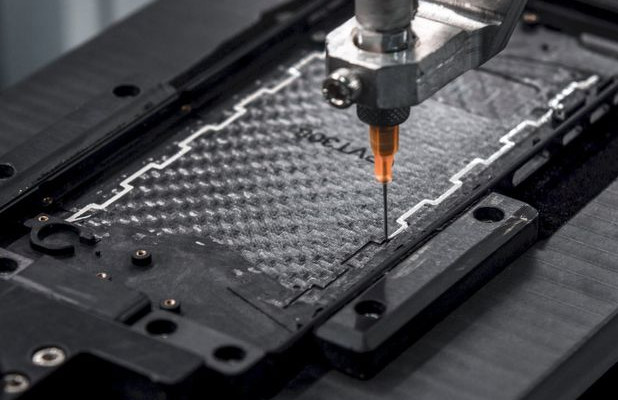
Waterjet Cutting
Waterjet cutting uses a high-pressure stream of water mixed with abrasive particles to cut carbon fiber. It is effective for intricate shapes and thick sheets (up to 50 mm). Operating pressures range from 40,000–60,000 psi, with feed rates of 100–500 mm/min. This method reduces thermal damage but may cause delamination if starting holes are not pre-drilled.
Turning
CNC turning is used for cylindrical carbon fiber parts, such as rods or tubes. Tools like cubic boron nitride (CBN) or PCD are employed, with cutting speeds of 20–50 m/min and feed rates of 0.05–0.15 mm/rev. Turning requires precise tool geometry to achieve smooth surface finishes.
Grinding
Grinding is used for finishing operations to achieve tight tolerances and smooth surfaces. Diamond grinding tools are recommended, with wheel speeds of 20–30 m/s and low feed rates (0.01–0.05 mm/pass). Coolants are often applied to reduce heat and prevent resin degradation.
Key Machining Parameters
Optimizing machining parameters is essential for achieving high-quality carbon fiber components. The following table summarizes typical parameters for common CFRP machining processes.
| Process | Tool Material | Cutting Speed | Feed Rate | Depth of Cut |
|---|---|---|---|---|
| Milling | Diamond-coated, PCD | 10,000–20,000 RPM | 0.05–0.2 mm/rev | 0.1–1.0 mm |
| Drilling | Carbide, Diamond-coated | 30–60 m/min | 0.02–0.1 mm/rev | 0.5–2.0 mm |
| Waterjet Cutting | Abrasive (Garnet) | N/A (40,000–60,000 psi) | 100–500 mm/min | Up to 50 mm |
| Turning | CBN, PCD | 20–50 m/min | 0.05–0.15 mm/rev | 0.1–0.5 mm |
| Grinding | Diamond | 20–30 m/s | 0.01–0.05 mm/pass | 0.01–0.1 mm |
These parameters should be adjusted based on the specific CFRP grade, fiber orientation, and tool condition to minimize defects and maximize tool life.
Difficulties in Carbon Fiber Machining
Machining carbon fiber presents several difficulties due to its composite structure and material properties. The following sections detail the primary issues encountered and strategies to mitigate them.
Delamination
Delamination occurs when layers of carbon fibers separate from the resin matrix, compromising structural integrity. It is caused by excessive cutting forces or improper tool geometry. To minimize delamination, use sharp tools, low feed rates, and climb milling (conventional milling for composites). Pre-drilling pilot holes and using backing plates during drilling also help.
Tool Wear
The abrasive nature of carbon fibers causes rapid tool wear, reducing tool life and increasing costs. Standard steel tools dull quickly, so diamond-coated or PCD tools are recommended. Regular tool inspection and replacement, along with optimized cutting parameters, can extend tool life. For example, reducing cutting speed by 10–20% can double tool life in some cases.
Heat Generation
Carbon fiber has low thermal conductivity, leading to heat buildup during machining. Excessive heat (above 200°C) can degrade the resin matrix, causing fiber pull-out or surface damage. Coolants, such as water or water-soluble fluids, should be used to dissipate heat. High-speed machining with low feed rates also reduces contact time, minimizing heat generation.
Surface Quality Issues
Achieving a smooth surface finish is challenging due to fiber pull-out, fraying, or chipping. Surface roughness (Ra) values typically range from 0.8–3.2 µm after machining, depending on the process. Using sharp, high-precision tools and fine-tuning parameters (e.g., lower feed rates) improves surface quality. Post-machining processes like sanding or polishing may be required for critical applications.
Dust and Health Hazards
Machining carbon fiber generates fine dust, which is harmful to lungs and can cause electrical shorts in equipment. Effective dust extraction systems and personal protective equipment (PPE), such as respirators and gloves, are essential. Wet machining reduces airborne dust but may introduce cleaning challenges due to the porous nature of CFRPs.
Best Practices for Carbon Fiber Machining
To achieve high-quality results, manufacturers must adopt specialized techniques and adhere to best practices. The following guidelines ensure precision and efficiency in CFRP machining.
Tool Selection
Use diamond-coated, PCD, or carbide tools designed for composites. For example, downcut endmills or compression cutters reduce chipping and delamination. Tool geometry, such as high helix angles (30–60°), minimizes friction and improves chip evacuation.
Workholding
Firm clamping or vacuum tables prevent material movement during machining, reducing vibration and defects. Ensure clamps do not crush the material, as CFRPs are brittle. Backing plates or sacrificial layers can support the workpiece during drilling or cutting.
Parameter Optimization
Adjust cutting speed, feed rate, and depth of cut based on the CFRP grade and fiber orientation. For unidirectional fibers, machine parallel to the fibers to minimize fraying. Automated systems, such as on-machine probing, can monitor tolerances and adjust parameters in real time.
Coolant Application
Use water-based coolants or mist systems to reduce heat and flush debris. Avoid oil-based coolants, as they may contaminate the porous CFRP surface, affecting subsequent bonding or coating processes.
Inspection and Quality Control
Regularly inspect machined surfaces for delamination, fiber pull-out, or dimensional inaccuracies using tools like calipers, micrometers, or coordinate measuring machines (CMMs). Non-destructive testing, such as ultrasonic inspection, can detect internal defects.
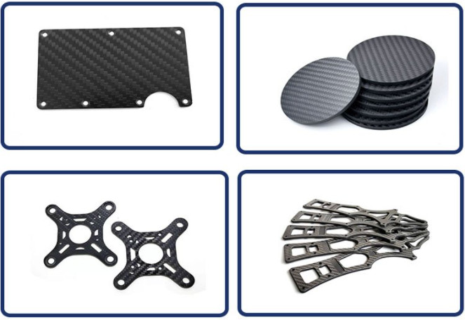
Applications of Carbon Fiber Machining
Machined carbon fiber components are critical in various industries. In aerospace, CFRPs are used for aircraft wings, fuselage sections, and satellite structures, requiring tolerances as tight as ±0.05 mm. In automotive, carbon fiber panels and chassis components enhance performance and fuel efficiency. Sporting goods, such as bicycle frames and tennis rackets, benefit from CFRP’s lightweight and durable properties. Medical devices, including prosthetics and imaging equipment, leverage carbon fiber’s X-ray transparency and strength.
Conclusion
Carbon fiber machining is a complex process requiring specialized tools, precise parameters, and careful consideration of material properties. By understanding the types of machining processes—milling, drilling, waterjet cutting, turning, and grinding—and addressing difficulties like delamination, tool wear, and heat generation, manufacturers can produce high-quality CFRP components. Adopting best practices, such as using diamond-coated tools, optimizing parameters, and implementing effective dust control, ensures precision, efficiency, and safety. This guide provides a systematic framework for mastering carbon fiber machining across various applications.