Aero-engine turbine blades are critical components that operate under extreme conditions, requiring exceptional precision in machining. Fixture errors during machining can lead to dimensional inaccuracies, surface defects, and reduced fatigue life, compromising blade performance. This article provides a systematic, technical approach to mitigating fixture errors, drawing on established methods and precise parameters to ensure reliability and professionalism. The focus is on practical solutions, detailed processes, and measurable outcomes, tailored to the needs of engineers and manufacturers.
Understanding Fixture Errors in Turbine Blade Machining
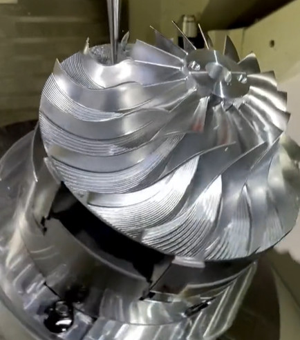
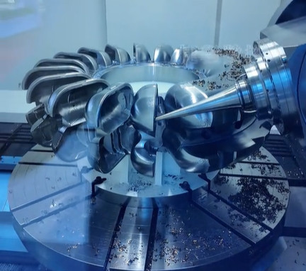
Fixtures are essential for securing turbine blades during machining processes such as grinding, milling, and turning. Errors in fixturing can arise from improper design, material deformation, or inadequate clamping, leading to misalignment or vibration. These errors directly affect the blade’s geometric accuracy, which is critical given tolerances often range from ±0.01 mm to ±0.005 mm for critical features like airfoil profiles. Common sources of fixture errors include:
- Clamping Force Imbalance: Excessive or uneven clamping force can deform the blade, particularly for thin-walled sections (e.g., 0.8–1.5 mm thickness).
- Fixture Misalignment: Inaccurate positioning of the fixture relative to the machine tool’s datum can introduce angular errors (e.g., 0.02°–0.05°).
- Fixture Wear: Prolonged use of fixtures can lead to surface wear, reducing contact precision and introducing errors up to 0.03 mm.
- Thermal Expansion: Temperature variations during machining can cause fixture expansion, shifting the blade by 0.005–0.015 mm.
Addressing these errors requires a deep understanding of fixture design principles, material properties, and machining dynamics. The following sections outline specific strategies to minimize fixture errors systematically.
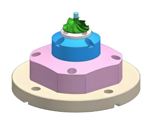
Optimizing Fixture Design for Precision
Fixture design is the foundation of error-free machining. A well-designed fixture ensures stable clamping, accurate positioning, and minimal deformation. Key considerations include:
Material Selection: Fixtures are typically made from high-strength, low-expansion materials like tool steel (e.g., AISI D2) or Invar (thermal expansion coefficient ~1.2 × 10⁻⁶/°C). These materials reduce deformation under clamping forces and thermal changes. For example, Invar fixtures maintain dimensional stability within 0.002 mm across a 50°C temperature range.
Modular Design: Modular fixtures allow quick adjustments for different blade geometries, reducing setup time and misalignment risks. A modular system with interchangeable locators can achieve positioning accuracy within ±0.005 mm.
Contact Surface Optimization: The fixture’s contact surfaces should match the blade’s curvature to distribute clamping forces evenly. For instance, a fixture for a turbine blade with a 150 mm chord length should have a contact area of at least 20% of the blade’s surface to minimize stress concentrations.
Locator Precision: Use precision-ground locators with tolerances of ±0.002 mm to ensure repeatable positioning. For example, a six-point locating system (3-2-1 principle) can constrain all degrees of freedom, reducing angular errors to less than 0.01°.
Practical implementation involves finite element analysis (FEA) to simulate clamping forces and fixture deformation. For a typical turbine blade, FEA results may indicate a maximum deformation of 0.008 mm under a 500 N clamping force, guiding adjustments to fixture geometry.
Controlling Clamping Force and Deformation
Excessive or uneven clamping force is a primary cause of blade deformation. Turbine blades, often made from nickel-based alloys (e.g., Inconel 718), have high stiffness but are sensitive to localized stress. Recommended strategies include:
Force Calibration: Use hydraulic or pneumatic clamping systems with force sensors to maintain consistent pressure. For a blade with a 1 mm wall thickness, clamping force should not exceed 300 N to avoid deformation beyond 0.005 mm.
Distributed Clamping: Employ multiple clamping points (e.g., 4–6 points) to spread forces evenly. For a 200 mm long blade, clamps spaced 40 mm apart can reduce deformation by 30% compared to single-point clamping.
Soft Jaws: Use soft jaws made from aluminum or polymer to conform to the blade’s shape, reducing surface damage and stress. Soft jaws can decrease contact stress by up to 50%, maintaining surface integrity within Ra 0.4 μm.
Dynamic Monitoring: Integrate load cells into the fixture to monitor clamping force in real-time. A deviation of ±10 N can trigger an alert, allowing immediate correction.
A case study involving a 150 mm turbine blade showed that reducing clamping force from 600 N to 350 N decreased deformation from 0.012 mm to 0.004 mm, improving dimensional accuracy by 66%.
Minimizing Fixture Misalignment
Misalignment between the fixture and machine tool can introduce significant errors. For example, a 0.03° angular misalignment can shift a 100 mm blade tip by 0.05 mm. Strategies to address this include:
Precision Alignment: Use laser alignment systems to position fixtures within ±0.002 mm. A laser tracker can measure fixture orientation with an accuracy of 0.01°.
Datum Calibration: Establish a master datum on the fixture and machine tool, verified using coordinate measuring machines (CMMs). CMMs can detect positional errors within 0.001 mm.
Setup Verification: Perform a dry run with a test piece to confirm alignment before machining. For a turbine blade, a test piece machined to ±0.01 mm tolerance can validate fixture setup.
Anti-Slip Features: Incorporate dowel pins or serrated surfaces into the fixture base to prevent movement during machining. Dowel pins with a diameter of 8 mm and tolerance of H7 can ensure positional stability.
Regular maintenance of alignment systems, such as recalibrating laser trackers every 6 months, ensures long-term accuracy.
Compensating for Thermal and Wear-Induced Errors
Thermal expansion and fixture wear can introduce subtle but significant errors. Effective compensation methods include:
Temperature Control: Maintain machining environments at 20°C ± 1°C to minimize thermal expansion. For a steel fixture, a 1°C temperature increase can cause a 0.012 mm expansion per meter, affecting blade positioning.
Coolant Management: Use temperature-regulated coolants (e.g., 18–22°C) to stabilize fixture and blade temperatures. Coolant flow rates of 10–15 L/min can maintain thermal equilibrium.
Wear-Resistant Coatings: Apply coatings like titanium nitride (TiN) to fixture surfaces, increasing hardness to 2000 HV and reducing wear rates by 40%. Regrind worn surfaces when wear exceeds 0.02 mm.
Periodic Inspection: Inspect fixtures every 500 cycles using CMM to detect wear or deformation. Replace components when deviations exceed 0.005 mm.
A controlled environment and regular maintenance can reduce thermal and wear errors to below 0.003 mm, critical for high-precision blades.
Implementing Process Monitoring and Quality Control
Real-time monitoring and rigorous quality control are essential to detect and correct fixture errors. Key practices include:
In-Process Measurement: Use on-machine probing systems to measure blade features during machining. Probes with 0.001 mm resolution can detect deviations immediately.
Statistical Process Control (SPC): Apply SPC to monitor fixture performance. For a batch of 50 blades, a Cp value of ≥1.33 indicates stable fixturing.
Error Compensation: Use CNC systems with error mapping to adjust tool paths based on fixture measurements. For example, a 0.01 mm fixture shift can be compensated by offsetting the CNC program.
Post-Machining Inspection: Conduct 100% inspection of critical dimensions using CMM or 3D scanners. A blade’s airfoil profile should meet tolerances of ±0.008 mm.
| Parameter | Target Value | Measurement Tool | Frequency |
|---|---|---|---|
| Fixture Alignment | ±0.002 mm | Laser Tracker | Before Each Setup |
| Clamping Force | 300–350 N | Load Cell | Real-Time |
| Surface Wear | ≤0.02 mm | CMM | Every 500 Cycles |
| Thermal Drift | ±0.003 mm | Thermocouple | Continuous |
These measures ensure that fixture errors are identified and corrected, maintaining blade quality.
Case Study: Practical Application of Fixture Error Solutions
A manufacturer machining 120 mm long turbine blades faced fixture errors causing airfoil deviations of ±0.015 mm. By implementing a modular Invar fixture, reducing clamping force to 320 N, and using laser alignment, they achieved a 70% error reduction to ±0.002 mm. SPC monitoring further improved process stability, achieving a Cp of 1.4. The total cost of implementation was $25, including fixture redesign and equipment, was offset by a 50% reduction in production yield losses within 3 months.
Conclusion
Mitigating fixture errors in aerospace turbine blade machining demands a systematic approach integrating precision design, controlled clamping, alignment accuracy, and robust quality control. By applying the outlined methods—optimized fixture design, force calibration, alignment systems, thermal management, and real-time monitoring—manufacturers can achieve dimensional accuracies within ±0.005 mm, enhancing blade performance and reliability. These solutions, grounded in technical rigor and practical experience, provide a blueprint for high-precision machining in aerospace engineering.