Centrifugal compressors are essential in industries like chemical processing, oil and gas, air separation, refrigeration, air conditioning, and power generation. These machines efficiently convert kinetic energy into pressure energy to compress gases. This article provides a detailed analysis of the working principles and key components of centrifugal compressors, focusing on their design and functionality.
Working Principle
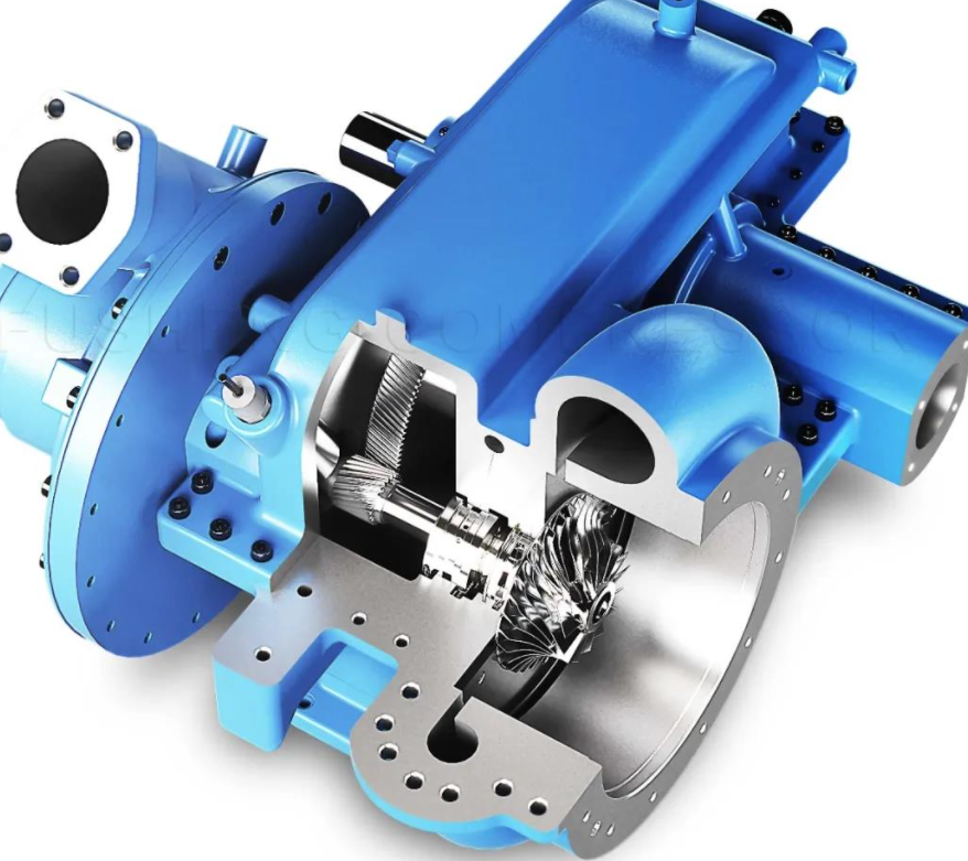
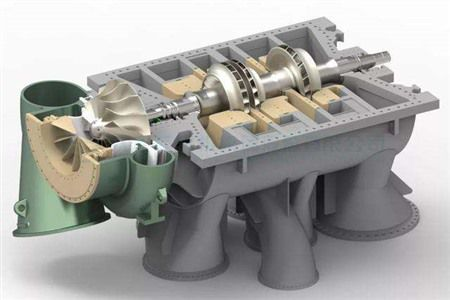
Centrifugal compressors operate by using a rotating impeller to accelerate gas, converting kinetic energy into pressure energy. The gas enters the compressor, is accelerated by the impeller, and then passes through a diffuser where its velocity decreases, increasing pressure. This process ensures efficient gas compression for various industrial applications.
Rotating Components
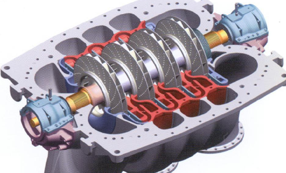
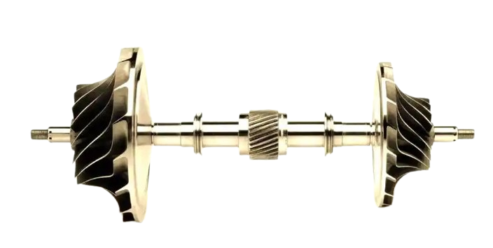
The rotating assembly, or rotor, is the core of a centrifugal compressor. It consists of several components, including the main shaft, impeller, balance disc, thrust disc, coupling, and sleeve, all working together to achieve efficient compression.
2.1 Main Shaft
The main shaft transmits power and maintains precise positioning between the rotor and stationary components, ensuring stable operation. Shaft designs vary based on structural requirements and are categorized into three types:
- Stepped Shaft: Features a diameter that decreases from the center to the ends, facilitating the installation of impellers, balance discs, and sleeves. Shoulders and keys ensure accurate impeller positioning and adequate rigidity.
- Whip Shaft: Includes annular grooves for flow paths without sleeves between stages. Impellers are positioned using shoulders and pins, balancing flow requirements and shaft rigidity.
- Smooth Shaft: Maintains a uniform diameter at the impeller mounting section, with no shoulders. Axial positioning is achieved using process snap rings, while impellers are secured with sleeves and keys.
Components are typically mounted using a hot-fitting method, where parts like impellers and balance discs are heated to expand their bores, allowing them to slide onto the shaft. Upon cooling, the parts contract for a secure fit, typically adhering to IT7 interference fit standards. To prevent loosening due to temperature changes or vibrations, screws or keys are used, with keys for impellers staggered at 180° to enhance shaft strength and rotor balance.
Shafts are commonly made from forged steel alloys such as 35CrMo, 40Cr, or 2Cr13, while impeller discs and covers use materials like 45, 35CrMoV, Cr17Ni2, or 1Cr18Ni9Ti for durability and performance.
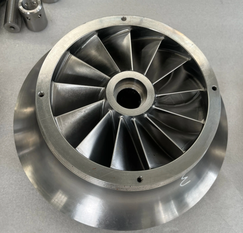
2.2 Impeller
The impeller is the heart of the compressor, responsible for accelerating gas. Its design significantly impacts performance, with common configurations including forward-leaning, backward-leaning, and radial impellers. The choice of impeller type depends on specific operating conditions to optimize efficiency and output.
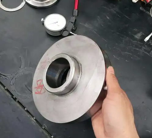
2.3 Balance Disc
The balance disc mitigates axial forces generated during compression, reducing the load on thrust bearings and extending their lifespan. Its design ensures uniform gas flow distribution and pressure balance.
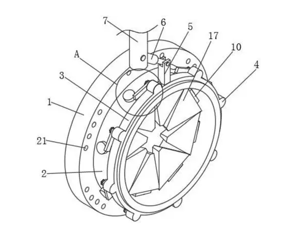
2.4 Thrust Disc
The thrust disc absorbs axial forces and works with thrust bearings to maintain precise axial positioning between the rotor, casing, and diffuser, ensuring operational stability.
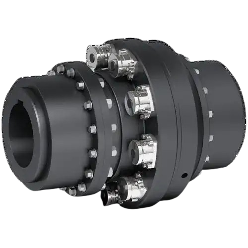
2.5 Coupling
Couplings connect the drive system to the main shaft, transmitting power smoothly. Depending on the application, rigid or flexible couplings are selected to ensure stable and efficient power transfer.
2.6 Sleeve (or Bushing)
Sleeves protect the main shaft from wear and deformation while securing components in place. Their design considers gas flow paths and axial positioning requirements for optimal performance.
Stationary Components
Stationary components form the structural backbone of centrifugal compressors, including the volute, return channel, diffuser, and sealing systems, each contributing to operational efficiency.
3.1 Return Channel
The return channel guides gas smoothly from one impeller to the next, minimizing energy losses. Common designs include uniform-thickness or variable-thickness guide vanes. The channel can be cast integrally with the cylinder or manufactured separately and bolted together.
3.2 Volute
The volute, or discharge chamber, collects gas from the final stage and directs it to an intercooler for cooling or to downstream pipelines. Modern designs favor volutes with cross-sectional areas that vary with gas flow to enhance efficiency compared to traditional constant-section chambers.
3.3 Diffuser
Located downstream of the impeller, the diffuser converts gas kinetic energy into pressure energy. Diffusers are classified as vaned or vaneless. Vaned diffusers offer steep performance curves but a narrower stable operating range, while vaneless diffusers provide flatter curves and broader stability.
Bearings
Bearings in centrifugal compressors are divided into radial and thrust types:
- Radial Bearings: Support the rotor and ensure stable rotation within the designated radial position.
- Thrust Bearings: Handle axial forces and maintain proper axial clearance between the rotor, casing, diffuser, and seals. They are typically installed at the low-pressure end of the rotor.
Sealing Systems
Sealing systems prevent gas leakage between stages and between the compressor and the external environment. Common types include labyrinth seals, gas seals, water ring seals, oil film seals, floating ring seals, and sleeve seals, each tailored to specific operational needs. Effective sealing enhances efficiency and extends the compressor’s service life.
Conclusion
Centrifugal compressors are vital to numerous industrial processes due to their efficient gas compression capabilities. Understanding their rotating and stationary components, bearings, and sealing systems provides valuable insights into their operation. This knowledge supports better design, maintenance, and performance optimization, ensuring reliability and efficiency in demanding applications.