Centrifugal compressors are critical components in various industries, known for their reliability, high pressure ratios, and compact design. This article provides a detailed overview of their structure, functionality, and applications, supported by key parameters and recent advancements. Designed for engineers and technical professionals, the content emphasizes precision and clarity, drawing from authoritative sources to ensure accuracy.
Structure of Centrifugal Compressors
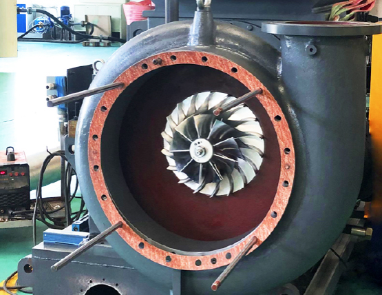
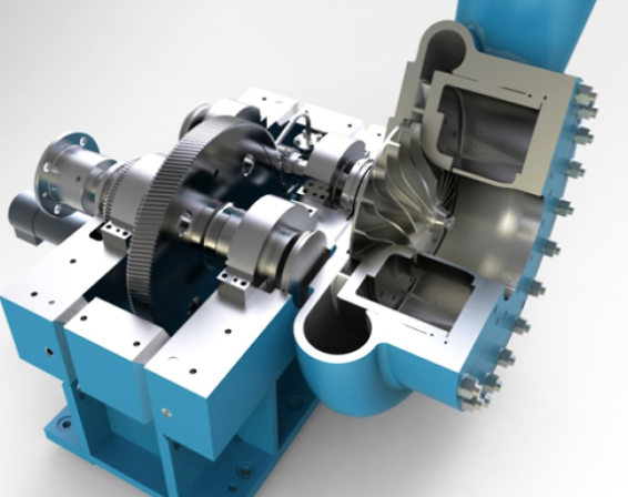
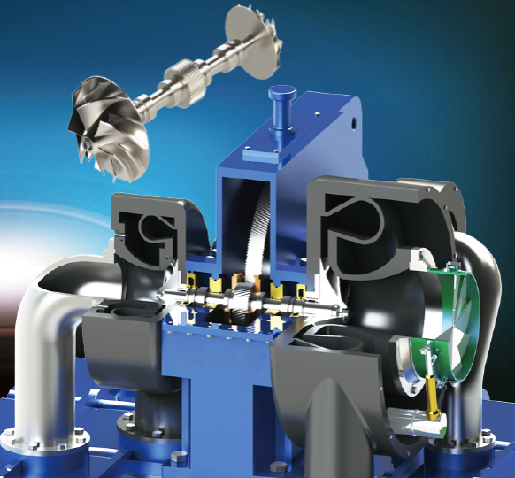
Centrifugal compressors consist of several key components that work together to compress gas efficiently. The primary elements include the impeller, diffuser, volute, and casing, each designed to optimize aerodynamic and structural performance.
- Impeller: The rotating component that imparts kinetic energy to the gas. Impellers can be open (without a cover plate) or closed (with a cover plate), with closed designs being common in multistage compressors for enhanced efficiency.
- Diffuser: Converts the high-velocity gas from the impeller into static pressure. Vaneless or vaned diffusers are used, with vaned diffusers improving efficiency in specific operating conditions.
- Volute: Collects the compressed gas and directs it to the outlet, minimizing losses.
- Casing: Houses the internal components, designed to withstand high pressures and ensure alignment.
- Shaft and Bearings: Support the impeller’s high-speed rotation, often using magnetic or active bearings for reduced friction in advanced designs.
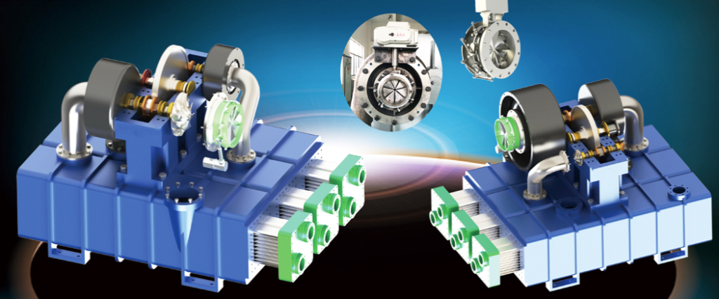
The structural design varies based on the application. For example, compressors in high-pressure environments, such as gas injection systems, may feature robust materials like high-strength alloy steel or stainless steel for corrosion resistance. Recent designs, such as those for CO2 heat pumps, incorporate magnetic bearings and compact structures to enhance efficiency and reduce maintenance.
Function of Centrifugal Compressors
Centrifugal compressors operate by accelerating gas through a rotating impeller, converting kinetic energy into pressure energy. The process follows these stages:
- Gas Intake: Gas enters the impeller’s eye axially or radially, depending on the inlet configuration.
- Energy Transfer: The impeller’s rotation increases the gas’s velocity, imparting kinetic energy proportional to the square of the impeller’s tip speed.
- Pressure Conversion: The diffuser slows the gas, converting kinetic energy into static pressure.
- Discharge: The volute or collector directs the compressed gas to the outlet for downstream use.
Key performance parameters include pressure ratio, flow rate, and efficiency, which are influenced by impeller geometry, rotational speed, and diffuser design. For instance, a compressor with a pressure ratio of 4.4 and an isentropic efficiency of 80–85% is typical for industrial applications. The flow coefficient, defined as the ratio of volumetric flow rate to impeller diameter and speed, is a critical dimensionless parameter for assessing flow capacity.
| Parameter | Description | Typical Range |
|---|---|---|
| Pressure Ratio | Ratio of discharge pressure to inlet pressure | 3–12 |
| Flow Coefficient | Dimensionless measure of flow capacity | 0.01–0.15 |
| Isentropic Efficiency | Ratio of ideal to actual work required | 77–85% |
| Rotational Speed | Impeller speed affecting performance | 3,000–30,000 RPM |
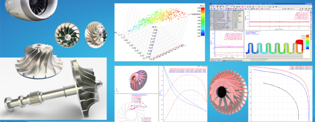
Recent advancements, such as the use of computational fluid dynamics (CFD), have improved performance prediction by analyzing flow behavior and optimizing blade angles. For example, reducing the inlet flow angle can minimize separation zones, enhancing efficiency by up to 2% in some designs.
Applications of Centrifugal Compressors
Centrifugal compressors are versatile, serving industries ranging from aerospace to oil and gas. Their ability to handle large volumes and achieve high pressure ratios makes them ideal for specific applications.
- Turbochargers: Used in automotive and marine engines to boost power by compressing intake air. A typical turbocharger compressor operates at speeds up to 210,000 RPM, achieving a 34% increase in choke flow with optimized designs.
- Gas Turbines: Provide compressed air for combustion, requiring high reliability and efficiency. Titanium alloys are often used for impellers in these applications due to their strength and corrosion resistance.
- Oil and Gas: Employed in gas injection and pipeline transmission, handling pressures up to 44.1 MPa (450 ata) for enhanced oil recovery.
- Refrigeration and Air Conditioning: Used in large-scale systems with refrigerants like CO2, where compact designs with magnetic bearings improve efficiency and reduce environmental impact.
- Aerospace: Power auxiliary units in aircraft, demanding lightweight and high-performance compressors.
Each application requires tailored designs. For instance, CO2 heat pump compressors use two-stage impellers and magnetic bearings to manage high pressures (4–6 MPa) and achieve pressure ratio increases of 12–38.6% with inlet pressure variations.
Design Parameters and Optimization
Designing centrifugal compressors involves balancing aerodynamic performance, structural integrity, and cost. Key parameters include impeller blade number, hub diameter, blade angle, and diffuser width. Optimization techniques, such as multidisciplinary optimization (MDO) and CFD, are widely used to enhance performance.
| Parameter | Impact | Optimization Approach |
|---|---|---|
| Blade Number | Affects flow uniformity and efficiency; 12–30 blades optimal | CFD analysis and genetic algorithms |
| Hub Diameter | Influences Mach number and turbulence; 60 mm optimal in some designs | Response Surface Method |
| Blade Angle | Controls flow separation; 45° backsweep improves slip factor | Full factorial analysis |
| Diffuser Width | Impacts pressure recovery; 70% of blade exducer width optimal | Parametric studies |
Recent studies have shown that configurations with 12 blades and a 60 mm hub diameter can improve pressure profiles by 36%. Additionally, double-splitter blade designs increase pressure ratios from 4.1 to 4.4, with efficiency gains of 2%. These advancements are supported by tools like ANSYS CFX and genetic algorithms, which reduce design time and costs compared to experimental methods.
Recent Advancements and Trends
Modern centrifugal compressor designs leverage numerical simulations and artificial intelligence to optimize performance. Key trends include:
- Numerical Simulations: CFD tools like ANSYS CFX and FLUENT enable precise flow analysis, reducing reliance on costly experimental testing.
- AI and Machine Learning: Artificial neural networks predict performance based on limited sample data, improving design efficiency.
- Eco-Friendly Designs: Compressors for CO2 heat pumps use natural refrigerants, aligning with environmental regulations.
- High-Speed Bearings: Magnetic bearings reduce friction and maintenance, critical for high-pressure applications like CO2 cycles.
These advancements have led to compressors with broader operating ranges, higher efficiencies (up to 87% in some designs), and reduced weights, particularly in aerospace and turbocharger applications.
Conclusion
Centrifugal compressors are vital to industries requiring efficient gas compression, from turbochargers to CO2 heat pumps. Their structure, centered around the impeller and diffuser, is optimized for high pressure ratios and reliability. Functionality hinges on precise energy transfer, governed by parameters like flow coefficient and rotational speed. Applications span diverse sectors, with recent advancements in CFD and AI driving performance improvements. By understanding and optimizing key design parameters, engineers can develop compressors that meet stringent performance and environmental requirements.