
Fatigue failure is a prevalent issue in mechanical components, accounting for 50% to 90% of mechanical part failures. In aero-engines, centrifugal impellers are particularly susceptible to fatigue cracks due to aerodynamic forces and high-speed centrifugal stresses. Such cracks can propagate, leading to material loss or catastrophic failure, potentially damaging adjacent components. This study investigates a specific case of centrifugal impeller hub failure in an aero-engine, where abnormal operation was detected during field use after 972 hours and 53 minutes of cumulative operation. The impeller, made of 2Cr13 stainless steel with a hardness specification of 28–35 HRC, exhibited material loss at the hub. Through systematic macroscopic and microscopic analyses, including fractography, metallography, and hardness testing, the failure was identified as high-cycle fatigue initiated by corrosion on the hub’s front surface. This analysis highlights the critical role of environmental factors in fatigue failure and the effectiveness of protective measures.
Experimental Methodology
The investigation involved a comprehensive examination of the failed centrifugal impeller to determine the failure mechanism and root cause. The methodology included visual inspection, fractographic analysis, metallographic examination, and hardness testing, as detailed below.
Visual Inspection of the Impeller
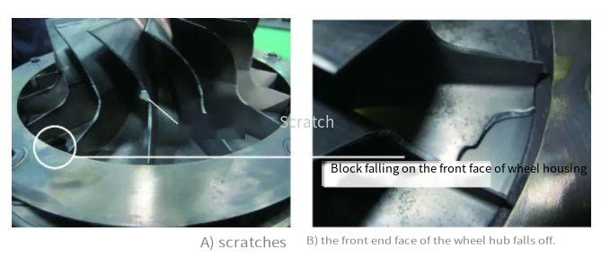
The centrifugal impeller, a bonded structure comprising a guide vane and impeller with 16 blades, exhibited material loss at the hub between two blades. Adjacent blades showed significant scratch marks on the guide vane edges. Two radial cracks were observed near the blade roots on the back side of two consecutive blades, with crack propagation paths similar to the material loss fracture surface. The cracks exhibited radial extension with an arc-shaped circumferential turn at their ends. The hub’s front surface displayed dense black spots and pitting, while the rear surface retained a smooth, machined appearance.
Fractographic Analysis of Material Loss
The fracture surface of the material loss was divided into three segments based on crack propagation: a radial fracture surface (Segment 1, ~17 mm long, representing early to mid-stage crack growth), a circumferential fracture surface (mid to late-stage growth), and a second radial fracture surface (Segment 2, instantaneous fracture zone). The recovered material fragment matched the loss site, with minor bending and wear but no significant material loss. Macroscopically, Segment 1 showed two arc-shaped propagation steps originating from two fatigue sources on the hub’s front surface, located approximately 3.5 mm and 13.6 mm from the outer edge. Microscopically, fatigue source areas revealed corrosion pits (~50 μm deep) with multiple initiation points. The crack propagation zone displayed fine fatigue striations, while the instantaneous fracture zone exhibited characteristic dimple morphology, indicative of ductile fracture.
Fractographic Analysis of Cracks
Two cracks (1# and 2#) were analyzed. Crack 1# showed clear macroscopic fatigue arcs across the fracture surface, with fatigue initiation at approximately 16.8 mm from the outer edge on the hub’s front surface. Crack 2# exhibited a flatter fracture surface, similar to the material loss radial segment, with a fatigue source at ~3.5 mm from the outer edge. Both cracks displayed corrosion features at their initiation sites, with multiple point sources. The fatigue striation widths in the propagation zones of both cracks were comparable to those in the material loss fracture.
Surface Corrosion Analysis
The hub’s front surface exhibited significant corrosion, with macroscopic pitting and microscopic intergranular corrosion pits observed under scanning electron microscopy (SEM). Energy-dispersive spectroscopy (EDS) analysis of the corrosion pits detected elevated levels of chlorine (Cl⁻), indicating environmental corrosion. The rear surface showed no such corrosion, retaining its original machined finish.
Metallographic and Hardness Testing
A metallographic sample was taken from beneath Crack 2# for analysis. The hub’s front surface showed multiple corrosion-induced black spots, while the rear surface remained unaffected. Both corroded and uncorroded samples revealed intergranular corrosion in the affected areas, with no abnormalities in the base material’s microstructure. Vickers hardness tests conducted near Crack 2# and on an intact hub section showed no significant differences, with values within the specified 28–35 HRC range.
| Element | Weight % | Atomic % |
|---|---|---|
| Cl | Significant presence | Detected |
| Fe | Predominant | Predominant |
| Cr | Present | Present |
| Location | Hardness (HRC) |
|---|---|
| Near Crack 2# | 30.5 ± 1.2 |
| Intact Hub | 31.0 ± 1.0 |
Results and Discussion
The centrifugal impeller’s material loss and associated cracks exhibited similar locations and propagation paths, with flat fracture surfaces displaying macroscopic fatigue arcs and microscopic fatigue striations. These characteristics confirm high-cycle fatigue as the failure mechanism. Both the material loss and cracks originated from corrosion pits on the hub’s front surface, with multiple initiation points. No metallurgical defects or hardness anomalies were detected, ruling out material-related causes. The concentrated failure locations across four consecutive blades suggest nodal diameter resonance, a vibration-induced phenomenon. The presence of chlorine in the corrosion pits indicates environmental corrosion, likely due to the engine’s operation in a marine environment with high chloride exposure.
The 2Cr13 stainless steel, a martensitic alloy, typically offers good corrosion resistance in atmospheric conditions. However, in chloride-rich environments, its passivation film is susceptible to breakdown, leading to pitting corrosion. Chlorine ions facilitate both the dissolution of the passivation layer and direct anodic dissolution of the metal, exacerbating corrosion. The corrosion pits acted as stress concentrators, promoting fatigue crack initiation under vibrational stresses. The absence of similar failures after applying a protective paint coating to the hub confirms that corrosion was the primary initiator of the fatigue process.
Conclusion
The centrifugal impeller failure was characterized as high-cycle fatigue, with material loss and cracks originating from corrosion pits on the hub’s front surface. The failure was driven by severe surface corrosion in a chloride-rich environment, coupled with vibrational stresses, leading to fatigue crack initiation and propagation. Protective paint coating on the hub effectively mitigated further occurrences of this failure, underscoring the importance of environmental corrosion control in preventing fatigue-related failures in aero-engine components.