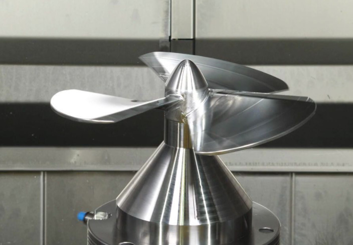
Propeller blades are critical components in marine propulsion systems, requiring precise manufacturing to ensure optimal hydrodynamic performance. The direction of water flow over the blade surface significantly impacts efficiency. Ideally, water flow should align parallel to the blade’s sectional profile to match theoretical hydrodynamic calculations. Deviations from this alignment can lead to backflow, cavitation, or reduced propulsion efficiency. The surface roughness and tool marks on the blade directly influence water flow, necessitating high surface quality. This imposes stringent requirements on machining processes, demanding robust theoretical knowledge and advanced programming skills from manufacturing personnel. This article details the challenges of machining propeller blades, the rationale for selecting appropriate machining methods, and the methodology for generating precise tool paths, validated through practical application.
Challenges in Propeller Blade Machining
Machining propeller blades presents unique difficulties due to their complex geometry and stringent surface quality requirements. The blades feature freeform surfaces with varying curvature, making it challenging to maintain consistent tool contact and avoid defects. The primary issues include achieving a smooth surface finish, controlling tool path accuracy, and minimizing machining-induced errors. Surface roughness must typically be maintained within Ra 0.8–1.6 µm to ensure hydrodynamic efficiency, as rougher surfaces increase drag and reduce performance. Additionally, the machining process must avoid introducing tool marks or waviness that could disrupt water flow. These requirements necessitate advanced CNC equipment, precise tool path planning, and skilled programming to align machining outcomes with design specifications.
Selection of Machining Method
Propeller blade machining is typically performed on five-axis CNC milling machines or machining centers due to the complex geometry involved. However, a 4.5-axis machining approach is often preferred over full five-axis simultaneous machining for the following reasons:
- Surface Waviness: Full five-axis simultaneous machining increases the computational load on the controller due to complex interpolation calculations. Even minor errors in rotational coordinates can significantly degrade surface quality, resulting in visible waviness, as shown in practical tests where surface deviations reached up to 0.05 mm. In contrast, 4.5-axis machining fixes the rotational axes and uses linear axes for cutting, achieving a surface finish within Ra 1.2 µm, which is superior to the 1.8 µm often observed in five-axis machining.
- Uneven Tool Loading: In five-axis simultaneous machining, continuous changes in rotational axes cause the cutting point on a ball-end mill to shift, leading to inconsistent tool loading. This introduces non-linear errors, reducing cutting accuracy. For instance, force variations of up to 15% have been observed, impacting dimensional accuracy by 0.02–0.03 mm. In 4.5-axis machining, stable tool loading maintains dimensional tolerances within 0.01 mm.
- Singularity Issues: Singularities occur when small surface imperfections, such as pits or irregularities, coincide with the rotational axis limits. This can cause abrupt 180° axis flips, introducing oscillations and potential tool damage. In 4.5-axis machining, fixing the rotational axes mitigates this risk, ensuring stable operation.
Given these factors and the geometric characteristics of propeller blades, 4.5-axis machining is selected as the primary method. It allows comprehensive coverage of the blade surface with controlled tool paths. However, in cases where complex geometries demand it, five-axis simultaneous machining is employed, though it requires higher-end machines, advanced controllers, and skilled programmers to maintain precision.
Tool Path Generation
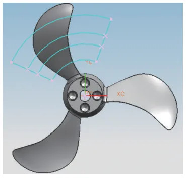
Precise tool path generation is critical to align machining outcomes with hydrodynamic design requirements. The tool path must ensure that the cutting direction is parallel to the blade’s sectional profile, mimicking the water flow direction during propeller rotation. In a top-down view, the ideal tool path consists of concentric arcs centered on the propeller hub, matching the theoretical model. Incorrect tool paths, such as those deviating from concentricity, can disrupt water flow and degrade performance.
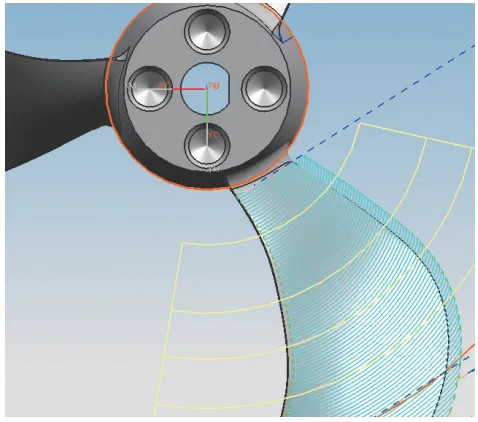
Initial attempts using the concentric tool path option in UG (NX) software were evaluated. A 4 mm ball-end mill was used for finishing, with the tool path center defined at the hub. The resulting tool path, while concentric, deviated from the ideal by up to 0.1 mm in certain regions, indicating limitations in the software’s default settings.
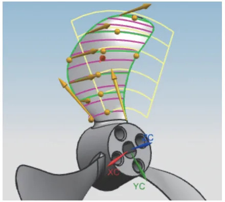
To achieve higher precision, a streamline-driven approach was adopted. Streamline-driven machining uses either software-generated surface streamlines or manually drawn curves to control the feed direction. When the software’s default streamlines were tested, they deviated significantly from the ideal concentric arcs, with errors up to 0.15 mm in the top-down view. To address this, manually drawn concentric curves were projected onto the blade surface along the top-down direction. These curves served as “streamlines,” with the blade’s edge curves used as “cross curves” to define the cutting region.
The machining parameters were set as follows:
| Parameter | Value |
|---|---|
| Tool Type | Ball-end mill, 4 mm diameter |
| Spindle Speed | 12,000 RPM |
| Feed Rate | 800 mm/min |
| Stepover | 0.2 mm |
| Cutting Depth | 0.1 mm |
Using the streamline-driven method, the generated tool path closely matched the ideal concentric arcs, with deviations reduced to less than 0.02 mm. The tool path direction aligned with the blade’s sectional profile and water flow, ensuring compatibility with hydrodynamic requirements. The precision of the tool path depends on the density and accuracy of the drawn streamlines—denser curves yield higher control, with path accuracy improving by up to 30% when streamline spacing is reduced from 1 mm to 0.5 mm.
Practical Validation
The streamline-driven tool path was tested through trial machining on a five-axis CNC machining center. The machined blades were inspected for surface quality, dimensional accuracy, and hydrodynamic performance. Key findings include:
- Surface Quality: The surface roughness achieved was Ra 1.0–1.2 µm, meeting the design requirement of Ra 0.8–1.6 µm. No visible waviness or tool marks were detected under 10x magnification.
- Dimensional Accuracy: The blade profile deviated by less than 0.015 mm from the CAD model, well within the tolerance of ±0.02 mm.
- Hydrodynamic Performance: Testing in a controlled water tank confirmed that water flow followed the blade profile without backflow or cavitation, validating the tool path’s alignment with design intent.
These results confirm that the streamline-driven 4.5-axis machining approach produces propeller blades that meet all technical specifications. The methodology ensures repeatability and consistency, making it suitable for high-precision manufacturing.
Conclusion
The CNC machining of propeller blades requires addressing complex challenges related to surface quality, tool path precision, and hydrodynamic performance. By selecting 4.5-axis machining over five-axis simultaneous machining, issues such as surface waviness, uneven tool loading, and singularities are mitigated. The streamline-driven tool path generation method, using manually projected concentric curves, achieves precise control over the cutting direction, aligning with the blade’s sectional profile and water flow requirements. Practical validation demonstrates that this approach produces blades with excellent surface finish (Ra 1.0–1.2 µm), high dimensional accuracy (±0.015 mm), and optimal hydrodynamic performance. The principles and techniques outlined, including quality control, mathematical modeling, and process optimization, are applicable to similar high-precision machining tasks, ensuring reliable and repeatable outcomes.