Impeller machining is a critical process in industries such as aerospace, automotive, and energy, where precision and performance are paramount. The profile error, defined as the deviation between the actual and designed surface contours of an impeller, directly impacts its aerodynamic or hydrodynamic efficiency, durability, and functionality. Controlling profile error requires a systematic approach that integrates advanced machining techniques, precise measurement, and robust quality assurance. This article provides a detailed, technical guide to minimizing profile errors in impeller machining, focusing on practical methods, specific parameters, and professional insights derived from industry experience.
Understanding Profile Error in Impeller Machining
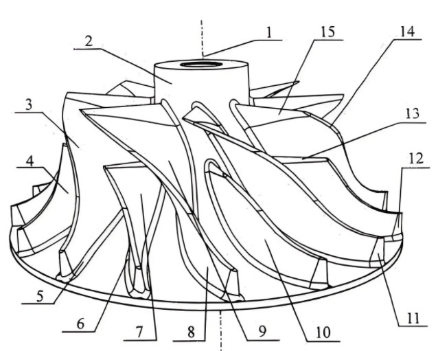
Profile error refers to the geometric deviation of the machined impeller surface from its intended design, often measured in terms of contour accuracy and surface finish. In impellers, which feature complex geometries like curved blades and intricate flow channels, even minor deviations can lead to performance losses, increased vibration, or premature wear. Profile errors arise from multiple factors, including tool wear, machine inaccuracies, material properties, and machining parameters. To address these, manufacturers must adopt a structured approach that encompasses machine setup, tool selection, cutting strategies, and post-machining inspection.
The acceptable profile error for impellers typically ranges from 0.01 mm to 0.05 mm, depending on the application. For example, aerospace impellers may require tolerances as tight as ±0.01 mm, while industrial pumps may allow up to ±0.03 mm. Achieving such precision demands a deep understanding of the machining process and its influencing factors, which are explored in the following sections.
Machine Setup and Calibration
Proper machine setup is the foundation for minimizing profile errors. Computer Numerical Control (CNC) machines, particularly 5-axis machining centers, are commonly used for impeller machining due to their ability to handle complex geometries. However, improper setup can introduce errors that propagate through the machining process.
Machine Calibration: Regular calibration of CNC machines ensures positional accuracy. For 5-axis machines, calibration involves verifying the alignment of rotary axes (A and B) and linear axes (X, Y, Z). A laser interferometer can be used to measure axis accuracy, with deviations corrected to within 0.005 mm. Calibration should be performed at least quarterly or after significant maintenance.
Workpiece Fixturing: Secure and precise fixturing prevents vibration and misalignment. Vacuum chucks or customized jigs are preferred for impellers, ensuring the workpiece remains stable during high-speed machining. The fixture’s contact surface should have a flatness tolerance of less than 0.02 mm to avoid distortion.
Thermal Stability: Temperature fluctuations in the machining environment can cause thermal expansion in the machine or workpiece, leading to profile errors. Maintaining a workshop temperature of 20±1°C and using coolant with a stable temperature (e.g., 18–22°C) mitigates this issue. Machines equipped with thermal compensation systems can further reduce errors by adjusting for thermal expansion in real time.
Tool Selection and Maintenance
The choice of cutting tools significantly affects profile accuracy. Impellers are typically machined from materials like stainless steel, titanium, or aluminum alloys, each requiring specific tool characteristics.
Tool Material: Carbide tools with coatings such as TiAlN (Titanium Aluminum Nitride) are ideal for machining impellers due to their high hardness and heat resistance. For titanium impellers, tools with a cutting edge radius of 0.02–0.04 mm reduce edge chipping and improve surface finish.
Tool Geometry: Ball-end mills are commonly used for finishing curved impeller surfaces, while tapered end mills are effective for roughing. A helix angle of 30–45° minimizes cutting forces and improves chip evacuation. Tool overhang should be kept below 3 times the tool diameter to reduce deflection, which can cause profile errors of up to 0.03 mm.
Tool Wear Monitoring: Tool wear directly contributes to profile errors. Regular inspection using a tool presetter or optical microscope can detect wear exceeding 0.1 mm, prompting tool replacement. Advanced systems like in-process tool monitoring can measure wear in real time, reducing errors by up to 20%.
Tool Path Optimization: CNC programming should incorporate adaptive tool paths that adjust feed rates and cutting depths based on the impeller’s geometry. For example, a constant scallop height strategy with a step-over of 0.05–0.1 mm ensures uniform surface finish and minimizes profile deviations.
Machining Parameters
Optimizing machining parameters is critical for controlling profile errors. Key parameters include cutting speed, feed rate, depth of cut, and coolant usage. The following table summarizes recommended parameters for common impeller materials:
| Material | Cutting Speed (m/min) | Feed Rate (mm/tooth) | Depth of Cut (mm) | Coolant Type |
|---|---|---|---|---|
| Stainless Steel | 80–120 | 0.05–0.1 | 0.1–0.5 | Water-based emulsion |
| Titanium Alloy | 40–60 | 0.03–0.08 | 0.05–0.3 | High-pressure coolant |
| Aluminum Alloy | 200–300 | 0.1–0.2 | 0.5–1.0 | Mist coolant |
Cutting Speed: Excessive cutting speeds can cause thermal distortion, while low speeds increase tool wear. For stainless steel impellers, a cutting speed of 100 m/min balances efficiency and tool life.
Feed Rate: A feed rate that is too high can lead to surface roughness, while a low feed rate reduces productivity. A feed rate of 0.05 mm/tooth for titanium ensures a smooth finish with minimal error.
Depth of Cut: Shallow depths of cut (e.g., 0.1 mm for finishing) reduce cutting forces and improve profile accuracy. For roughing, deeper cuts (0.5–1.0 mm) are acceptable but require robust fixturing.
Coolant Usage: High-pressure coolant systems (e.g., 70–100 bar) enhance chip removal and reduce thermal errors, particularly for titanium alloys. Coolant flow rates of 20–30 L/min are recommended for consistent performance.
Quality Control and Inspection
Post-machining inspection is essential to verify profile accuracy and identify errors. Advanced measurement techniques ensure that impellers meet design specifications.
Coordinate Measuring Machines (CMM): CMMs equipped with touch probes or laser scanners measure profile errors with an accuracy of ±0.002 mm. Scanning the entire impeller surface provides a comprehensive error map, highlighting deviations in critical areas like blade edges.
Optical Metrology: Non-contact systems, such as white-light interferometry, offer high-resolution surface analysis. These systems detect micro-level errors (e.g., 0.005 mm) and are ideal for finishing processes.
Statistical Process Control (SPC): SPC techniques monitor machining consistency by analyzing profile error data from multiple parts. A control limit of ±0.02 mm ensures process stability, with deviations triggering corrective actions like tool replacement or parameter adjustment.
Inspection Frequency: For high-precision impellers, 100% inspection is recommended. For larger batches, a sampling rate of 10–20% using AQL (Acceptable Quality Level) standards ensures quality without excessive costs.
Material Considerations
The material properties of the impeller influence machining outcomes. Titanium alloys, for instance, have low thermal conductivity, leading to heat buildup that can cause profile errors. Pre-machining heat treatment (e.g., annealing at 700°C for 1 hour) reduces residual stresses, improving machinability. Stainless steel impellers, prone to work hardening, require lower cutting speeds to prevent surface defects. Aluminum alloys, while easier to machine, demand careful control of chip formation to avoid burrs that affect profile accuracy.
Material homogeneity is another factor. Variations in grain structure or inclusions can cause localized errors. Non-destructive testing (e.g., ultrasonic inspection) before machining identifies material defects, allowing adjustments in tool paths or parameters.
Process Integration and Workflow
A systematic workflow integrates all aspects of impeller machining to minimize profile errors. The process begins with CAD/CAM design, where the impeller’s geometry is optimized for manufacturability. Simulation software, such as Mastercam or Siemens NX, predicts tool paths and identifies potential error sources, reducing trial-and-error on the shop floor.
During machining, real-time monitoring systems track parameters like spindle load and vibration. A spindle load exceeding 80% indicates potential tool wear or instability, prompting immediate adjustments. Post-machining, a feedback loop integrates inspection data into the process, allowing continuous improvement. For example, if CMM data shows a recurring error of 0.02 mm on blade tips, programmers can adjust the tool path to compensate.
Documentation is critical for traceability. Maintaining records of machining parameters, tool life, and inspection results ensures consistency across production runs. A digital twin of the impeller, updated with real-time data, can further enhance process control by predicting error trends.
Practical Considerations
While the techniques above are effective, practical constraints must be addressed. For instance, high-precision machining increases production time, impacting costs. Balancing precision with efficiency requires prioritizing critical areas (e.g., blade leading edges) for tight tolerances while allowing looser tolerances in non-critical zones. Additionally, operator training is essential. Skilled machinists can identify subtle issues, such as tool chatter, that automated systems may miss.
Another consideration is equipment availability. Not all facilities have access to 5-axis CNC machines or advanced CMMs. In such cases, outsourcing inspection to certified labs or using portable metrology tools can maintain quality without significant capital investment.
Conclusion
Controlling profile error in impeller machining is a multifaceted challenge that demands precision, expertise, and a systematic approach. By optimizing machine setup, tool selection, machining parameters, and quality control, manufacturers can achieve profile accuracies within ±0.01–0.05 mm, meeting the stringent requirements of high-performance applications. Integrating these techniques into a cohesive workflow, supported by robust documentation and continuous feedback, ensures consistent quality and reliability. This guide provides a practical, experience-based framework for professionals seeking to enhance impeller machining precision, grounded in technical rigor and industry best practices.