Turbine impellers are critical components in turbomachinery, requiring high precision due to their complex geometries and demanding performance requirements. Optimizing CNC machining paths for turbine impellers enhances efficiency, reduces cycle times, and ensures dimensional accuracy. This article provides a systematic, technical approach to toolpath optimization, focusing on 5-axis CNC machining, tool selection, and process parameters, supported by detailed strategies and specific parameters.
Understanding Turbine Impeller Geometry
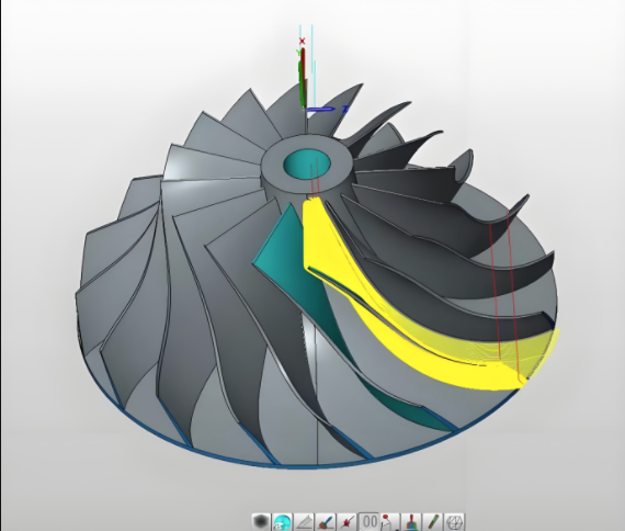
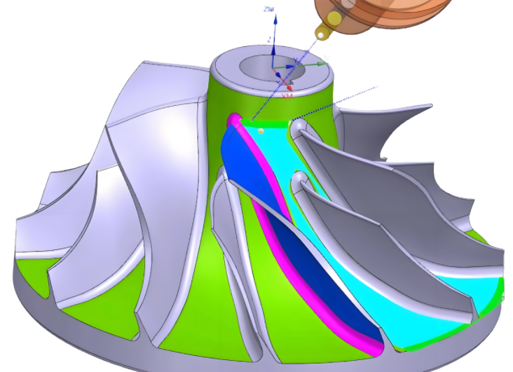
Turbine impellers feature intricate designs, including twisted blades, narrow flow channels, and varying hub-to-tip ratios. These components are typically made from materials like stainless steel, titanium, or aluminum alloys, which pose machining challenges due to their hardness and thermal properties. The geometry includes:
- Blades with significant torsion angles (up to 45°) and thin profiles (0.5–2 mm at the leading edge).
- Deep, tapered flow channels with widths as narrow as 5–10 mm.
- Hub surfaces with complex curvatures defined by NURBS (Non-Uniform Rational B-Splines).
These characteristics necessitate advanced machining strategies to avoid tool collisions, minimize vibrations, and achieve surface roughness (Ra) of 0.3–0.8 μm for aerodynamic performance.
Key Strategies for Toolpath Optimization
Optimizing CNC machining paths involves strategic planning of tool movements, cutting parameters, and machine capabilities. The following strategies are critical for turbine impeller machining.
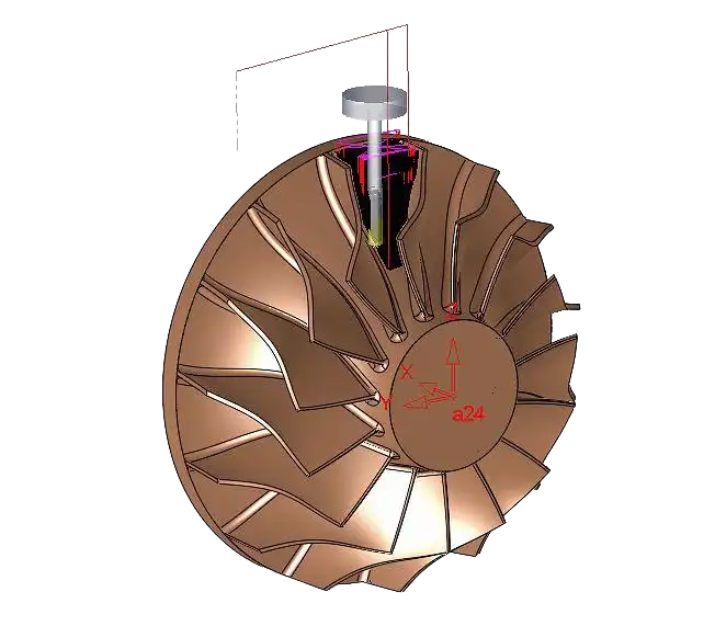
Adopting 5-Axis CNC Machining
5-axis CNC machines are essential for turbine impellers due to their ability to maneuver tools along five axes (X, Y, Z, A, B). This flexibility allows access to complex geometries in a single setup, reducing repositioning errors and cycle times. Key benefits include:
- Improved tool reach for deep channels (e.g., 50–100 mm depth).
- Reduced setup time by 30–40% compared to 3-axis machining.
- Enhanced precision with positional accuracy of ±0.005 mm.
For example, a 5-axis machine can maintain a constant lead angle (5–10°) during blade machining, minimizing tool deflection and ensuring uniform material removal.
Toolpath Types: Flank vs. Point Milling
Two primary toolpath strategies for impeller machining are flank milling and point milling. Each has specific applications based on blade geometry and machining requirements.
| Toolpath Type | Description | Applications | Advantages | Limitations |
|---|---|---|---|---|
| Flank Milling | Uses the side of a straight-edged tool to machine blade surfaces in a single pass. | Suitable for ruled surfaces with straight-line elements. | High efficiency; reduces cycle time by 20–30%; minimal tool wear. | Limited to simpler geometries; potential for overcutting on twisted blades. |
| Point Milling | Uses a ball-end or tapered tool, making multiple passes with point contact. | Ideal for complex, non-ruled surfaces with high curvature. | High precision (Ra 0.3–0.4 μm); suitable for intricate designs. | Longer cycle times (80–200 passes per blade); higher tool wear. |
For impellers with complex blade curvatures, point milling is preferred for its accuracy, while flank milling is used for roughing to maximize material removal rates (MRR) of 50–100 cm³/min.
Optimizing Cutting Parameters
Cutting parameters significantly influence machining efficiency and surface quality. Key parameters include spindle speed, feed rate, and step-over distance. Recommended settings for titanium impellers are:
- Spindle Speed: 8,000–12,000 RPM for roughing; 15,000–20,000 RPM for finishing.
- Feed Rate: 1,000–2,000 mm/min for roughing; 500–1,000 mm/min for finishing.
- Step-Over Distance: 0.1–0.3 mm for finishing to achieve Ra 0.3–0.8 μm.
These parameters balance material removal with tool life, reducing cycle times by up to 25% compared to empirical settings. For aluminum alloys, increase spindle speed to 18,000–25,000 RPM and feed rate to 2,000–3,000 mm/min to leverage the material’s lower hardness.
Dynamic Toolpath Strategies
Dynamic toolpaths, such as adaptive machining, maintain constant chip loads by adjusting tool engagement. This approach uses full axial depth cuts (5–10 mm) with light radial cuts (0.5–1 mm), reducing tool wear and improving surface finish. Benefits include:
- Extended tool life by 20–30%.
- Reduced machining time by 15–20% due to fewer passes.
- Minimized vibrations, critical for thin blades (0.5–1 mm thickness).
Adaptive machining adjusts toolpaths in real-time based on material conditions, ensuring consistent performance across varying blade thicknesses.
Tool Selection and Management
Tool selection is critical for optimizing impeller machining. The following considerations ensure effective material removal and surface quality.
Tool Types and Geometries
Common tools for impeller machining include:
- Ball-End Mills: Used for point milling; diameters of 4–10 mm for finishing complex surfaces.
- Tapered Ball-End Mills: Provide clearance for deep channels; taper angles of 2–5°.
- Lollipop Cutters: Suitable for undercut regions; neck clearance of 10–15 mm.
Coatings like TiAlN or AlCrN enhance tool life by 25–40% in high-temperature alloys, reducing wear at cutting speeds of 50–100 m/min.
Toolpath Smoothing
Smoothing techniques, such as PerfectCut, reduce abrupt tool movements by applying arcs to jagged geometries. This improves surface finish (Ra 0.2–0.4 μm) and reduces cycle time by 10–15% by minimizing deceleration on contours. Smoothing is particularly effective for blades with curvature radii of 5–20 mm.
Process Planning and Simulation
Effective process planning involves dividing the machining process into roughing, semi-finishing, and finishing stages to optimize efficiency and accuracy.
Roughing Strategies
Roughing removes excess material (70–80% of total volume) from the impeller blank. Key strategies include:
- Flow Channel Division: Divide channels into three sections (inlet, middle, outlet) to manage depth variations (10–50 mm).
- Plunge Milling: Uses Z-axis cuts for high MRR (100–150 cm³/min); effective for rigid machines.
- Spiral Toolpaths: Maintain consistent cutting loads in deep cavities, reducing tool deflection.
Roughing parameters: spindle speed of 6,000–10,000 RPM, feed rate of 1,500–2,500 mm/min, and depth of cut of 5–8 mm.
Finishing Strategies
Finishing ensures dimensional accuracy and surface quality. Techniques include:
- Parallel Toolpaths: Used for flat hub surfaces; step-over of 0.1–0.2 mm for Ra 0.3–0.5 μm.
- Radial Toolpaths: Effective for cylindrical surfaces; maintain tool engagement at 10–20% of diameter.
- Pencil Milling: Targets corners and blade roots, reducing residual material to 0.01–0.05 mm.
Finishing parameters: spindle speed of 15,000–20,000 RPM, feed rate of 500–800 mm/min, and step-over of 0.05–0.15 mm.
CAD/CAM Integration
CAD/CAM software (e.g., Unigraphics NX, CAMWorks) generates precise toolpaths and simulates machining to detect collisions. Simulation verifies:
- Toolpath accuracy within ±0.01 mm.
- Collision-free paths for blades with 5–10 mm spacing.
- G-code compatibility with 5-axis machines.
Software like MAX-PAC optimizes toolpaths for impellers, reducing programming time by 20–30%.
Quality Control and Validation
Ensuring impeller quality involves rigorous inspection and validation to meet tolerances of ±0.01 mm and surface roughness requirements.
Inspection Techniques
Common methods include:
- Coordinate Measuring Machines (CMM): Verify dimensional accuracy to ±0.005 mm.
- Non-Destructive Testing (NDT): Detect internal defects in high-stress areas.
- Surface Profilometry: Measure Ra values to ensure 0.3–0.8 μm.
Inspection frequency: 100% for critical dimensions (e.g., blade thickness), 10–20% sampling for surface finish.
Performance Testing
Impellers undergo performance mapping to validate aerodynamic efficiency and stress analysis to ensure operation at high RPMs (e.g., 15,000–75,000 RPM). Testing confirms:
- Pressure ratio within 1–2% of design specifications.
- No vibrational chatter at operational speeds.

Practical Implementation Example
Consider a titanium impeller with 12 blades, 100 mm diameter, and 50 mm channel depth. The machining process involves:
- Roughing: Use a 10 mm flat-end mill, 8,000 RPM, 2,000 mm/min feed rate, and 5 mm depth of cut to remove 80% material in 3 hours.
- Semi-Finishing: Employ a 6 mm ball-end mill, 12,000 RPM, 1,000 mm/min feed rate, and 0.5 mm step-over for 1.5 hours.
- Finishing: Use a 4 mm tapered ball-end mill, 18,000 RPM, 600 mm/min feed rate, and 0.1 mm step-over to achieve Ra 0.4 μm in 2 hours.
Total cycle time: approximately 6.5 hours, reduced by 25% using optimized parameters compared to empirical settings.
Conclusion
Optimizing CNC machining paths for turbine impellers requires a systematic approach, leveraging 5-axis machining, strategic toolpath selection, and precise cutting parameters. By integrating CAD/CAM software, dynamic toolpaths, and rigorous quality control, manufacturers can achieve high precision, reduce cycle times, and enhance impeller performance. This technical framework ensures efficient production of complex impellers, meeting the stringent demands of aerospace, energy, and marine applications.