The surface finish of molecular pump impellers is critical for their performance, directly impacting efficiency, durability, and operational stability. Achieving a high-quality surface finish requires precise control over machining processes, particularly through the optimization of cutting parameters. This article provides a detailed, technical guide on adjusting cutting parameters to improve the surface finish of molecular pump impellers, emphasizing practical experience, reliability, and systematic approaches.
Understanding Surface Finish in Molecular Pump Impellers
Surface finish refers to the texture and quality of a machined surface, typically measured by roughness parameters such as Ra (average roughness) and Rz (maximum height of the profile). For molecular pump impellers, a smooth surface is essential to minimize gas turbulence, reduce friction, and enhance vacuum performance. Poor surface finish can lead to increased wear, reduced efficiency, and potential failure in high-speed applications. The primary machining processes for impellers are CNC milling or turning, where cutting parameters like speed, feed rate, and depth of cut play a pivotal role in determining surface quality.
Key factors influencing surface finish include material properties, tool geometry, machine rigidity, and cutting parameters. Molecular pump impellers are often made from materials like aluminum alloys, titanium, or stainless steel, which require specific machining strategies to achieve optimal results. This guide focuses on achieving a surface roughness of Ra 0.2–0.8 µm, a common requirement for high-performance impellers.
Key Cutting Parameters and Their Effects
Cutting parameters are adjustable variables in the machining process that directly influence surface finish. These include cutting speed, feed rate, depth of cut, and tool path strategy. Each parameter is discussed below in detail, including its impact and recommended settings based on practical experience.
Cutting Speed
Cutting speed (Vc), measured in meters per minute (m/min), determines the velocity at which the cutting tool moves relative to the workpiece. Higher cutting speeds generally improve surface finish by reducing tool-workpiece contact time, minimizing vibrations and heat buildup. However, excessively high speeds can cause tool wear or thermal deformation, particularly in heat-sensitive materials like titanium.
For aluminum alloys (e.g., 6061-T6), a cutting speed of 200–300 m/min is recommended for milling with carbide tools. For stainless steel (e.g., 304), a range of 80–120 m/min is suitable to prevent excessive tool wear. Titanium alloys (e.g., Ti-6Al-4V) require lower speeds, typically 50–80 m/min, due to their low thermal conductivity. Maintaining consistent cutting speeds within these ranges ensures a balance between surface quality and tool life.
Feed Rate
Feed rate (f), measured in millimeters per tooth (mm/tooth), dictates the distance the tool advances per cutting edge. A lower feed rate typically produces a smoother surface by reducing the size of machining marks. However, an excessively low feed rate can increase machining time and cause rubbing, which degrades surface quality.
For finishing operations on molecular pump impellers, a feed rate of 0.05–0.15 mm/tooth is recommended for aluminum alloys, while 0.03–0.10 mm/tooth is suitable for stainless steel and titanium. Adjusting the feed rate based on tool diameter and spindle speed ensures optimal chip formation, reducing surface roughness.
Depth of Cut
Depth of cut (ap), measured in millimeters, refers to the thickness of material removed in a single pass. In finishing operations, a shallow depth of cut is preferred to minimize tool deflection and vibration, which can cause surface irregularities. For molecular pump impellers, a depth of cut of 0.1–0.5 mm is typically used during finishing passes to achieve a smooth surface.
Using multiple shallow passes rather than a single deep cut can further enhance surface quality. For example, for an aluminum impeller, three passes at 0.2 mm each are more effective than a single 0.6 mm cut. This approach reduces cutting forces and improves surface consistency.
Tool Path Strategy
The tool path strategy determines the pattern the cutting tool follows during machining. Common strategies for impeller machining include spiral, zigzag, and contour-parallel paths. For finishing operations, a spiral tool path is often preferred as it ensures continuous tool engagement, reducing surface imperfections caused by tool entry and exit.
A step-over distance (radial depth of cut) of 5–10% of the tool diameter is recommended for finishing to minimize cusp height and achieve a uniform surface. For example, with a 10 mm diameter tool, a step-over of 0.5–1 mm is ideal. Additionally, climb milling (where the tool rotation aligns with the feed direction) produces a better surface finish than conventional milling due to reduced chip recutting.
Material-Specific Considerations
The material of the molecular pump impeller significantly affects the choice of cutting parameters. Below is a summary of recommended parameters for common materials, based on practical machining experience.
| Material | Cutting Speed (m/min) | Feed Rate (mm/tooth) | Depth of Cut (mm) |
|---|---|---|---|
| Aluminum Alloy (6061-T6) | 200–300 | 0.05–0.15 | 0.1–0.5 |
| Stainless Steel (304) | 80–120 | 0.03–0.10 | 0.1–0.3 |
| Titanium Alloy (Ti-6Al-4V) | 50–80 | 0.03–0.10 | 0.1–0.3 |
These parameters are starting points and should be fine-tuned based on specific machine capabilities, tool conditions, and impeller geometry.
Tool Selection and Geometry
The choice of cutting tool and its geometry significantly impacts surface finish. For molecular pump impellers, solid carbide end mills or coated tools (e.g., TiAlN or AlTiN) are recommended due to their durability and precision. Key tool characteristics include:
- Number of Flutes: 4–6 flutes for aluminum to ensure smooth chip evacuation; 2–4 flutes for stainless steel and titanium to reduce cutting forces.
- Helix Angle: A 35–45° helix angle is ideal for finishing, balancing chip evacuation and surface quality.
- Edge Preparation: Polished or honed edges reduce friction and improve surface finish.
- Tool Diameter: Smaller diameters (6–12 mm) are preferred for finishing complex impeller geometries to reduce tool deflection.
Regular tool inspection and replacement are critical to maintaining consistent surface quality, as worn tools can introduce chatter marks and increase roughness.
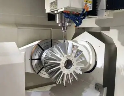
Machine Setup and Stability
Machine rigidity and setup are foundational to achieving a high-quality surface finish. Key considerations include:
- Workpiece Clamping: Secure clamping minimizes vibration. Vacuum chucks or custom fixtures are ideal for complex impeller shapes.
- Spindle Runout: Spindle runout should be less than 0.005 mm to prevent uneven cutting.
- Coolant Application: Flood coolant or minimum quantity lubrication (MQL) reduces heat and improves chip evacuation. For titanium, high-pressure coolant (70–100 bar) is recommended to prevent tool adhesion.
- Machine Calibration: Regular calibration of CNC machines ensures precise tool movement and consistent results.
Ensuring a stable machining environment minimizes external factors that could compromise surface finish.
Practical Implementation and Testing
Optimizing cutting parameters is an iterative process that requires testing and adjustment. The following steps outline a systematic approach:
- Initial Parameter Selection: Start with the recommended parameters from the table above, tailored to the impeller material.
- Test Machining: Perform a test cut on a sample workpiece, focusing on a small section of the impeller geometry.
- Surface Measurement: Use a profilometer to measure Ra and Rz values. Compare results against the target (Ra 0.2–0.8 µm).
- Parameter Adjustment: If roughness exceeds the target, reduce feed rate or depth of cut by 10–20% and retest. If tool wear is observed, lower cutting speed.
- Full Machining: Apply optimized parameters to the entire impeller, monitoring tool condition and surface quality throughout.
Documenting each test’s parameters and results builds a reliable database for future machining operations.
Common Issues and Solutions
While optimizing cutting parameters, certain issues may arise. Below is a table summarizing common problems and their solutions.
| Issue | Possible Cause | Solution |
|---|---|---|
| Excessive Surface Roughness | High feed rate or depth of cut | Reduce feed rate to 0.03–0.10 mm/tooth or depth of cut to 0.1–0.3 mm |
| Chatter Marks | Tool deflection or machine vibration | Increase machine rigidity, use shorter tools, or reduce spindle speed by 10% |
| Tool Wear | Excessive cutting speed | Lower cutting speed by 10–20 m/min and ensure proper coolant application |
Conclusion
Optimizing cutting parameters is a critical step in achieving a high-quality surface finish for molecular pump impellers. By carefully adjusting cutting speed, feed rate, depth of cut, and tool path strategy, manufacturers can achieve a surface roughness of Ra 0.2–0.8 µm, enhancing impeller performance and longevity. Material-specific parameters, proper tool selection, and a stable machine setup are essential for success. Through systematic testing and adjustment, machinists can develop reliable processes that deliver consistent results. This technical approach ensures precision, efficiency, and durability in molecular pump impeller production.