
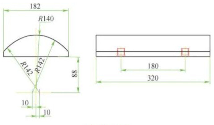
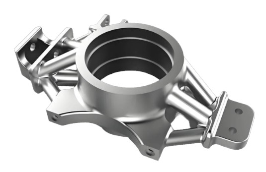
This article provides a detailed comparison of two machining approaches for processing multi-arc surface products, specifically a pendulum block with three distinct arc surfaces. The analysis focuses on the use of CNC turn-mill centers and conventional lathes, emphasizing process design, fixture development, and practical applications. The pendulum block, as shown in Figure 1, features an upper surface composed of three arc segments: one R140mm arc with its center aligned on the reference circle’s centerline and two R142mm arcs symmetrically positioned on either side. Additionally, the block includes two threaded hinge holes at its base for mounting. The goal is to evaluate which method best meets the machining requirements in terms of precision, efficiency, and practicality.
Overview of the Pendulum Block and Machining Requirements
The pendulum block is a complex component requiring precise machining of its multi-arc surfaces. The R140mm arc is concentric with the reference circle, while the two R142mm arcs are eccentric, with their centers offset by 10mm on either side of the centerline. The threaded hinge holes add further complexity, necessitating secure fixturing during machining. Key requirements include achieving high surface finish (roughness up to 1.6μm), dimensional accuracy, and efficient production, particularly for small to medium batch sizes. Two primary machining methods are considered: CNC turn-mill centers and conventional lathes with flexible fixtures.
CNC Turn-Mill Center Machining Process
CNC turn-mill centers combine turning and milling capabilities, offering versatility for complex geometries like the pendulum block. This method involves a single setup to machine all three arc surfaces, reducing setup time and improving consistency.
Process Analysis
The CNC turn-mill process uses a dedicated fixture to symmetrically clamp two pendulum blocks, enabling simultaneous machining. The R140mm arc is machined via turning, leveraging the machine’s rotational axis. The eccentric R142mm arcs are processed using follow-up milling, where the milling tool moves in sync with the workpiece’s rotation to form the arc surfaces.
Fixture Design and Clamping
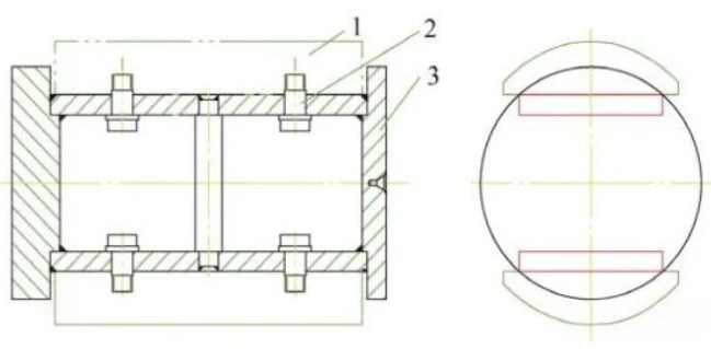
A specialized fixture, typically a frame structure, is designed to hold two pendulum blocks symmetrically, as illustrated in Figure 2. One end is clamped using a chuck, while the other is supported by a tailstock center. The fixture ensures the R140mm arc’s center aligns with the machine’s rotational axis for optimal dynamic balance. Clamping involves positioning the blocks on a locating plane, secured with bolts through the threaded hinge holes.
Machining the Arc Surfaces
R140mm Arc Surface: The workpiece rotates around the machine’s spindle, and the cutting tool feeds axially to form the concentric R140mm arc. This turning operation ensures high precision and surface quality due to continuous cutting.
R142mm Eccentric Arc Surfaces: These are machined using follow-up milling, where the milling tool follows a programmed path to create the eccentric arcs. The machine’s control system uses specific commands to offset the tool path, ensuring the arcs are accurately formed.
Tool Selection
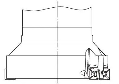
Milling the eccentric arcs requires a three-sided disc milling cutter, as shown in Figure 3. This tool has flat bottom and side edges, enabling it to mill small, flat segments that approximate the arc surface (a “line-to-arc” approach). The tool’s design ensures good flatness and straightness of the machined segments, contributing to overall arc accuracy.
Milling Parameters and Principles
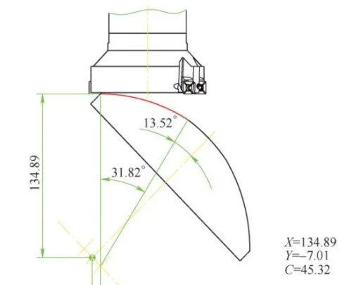
Eccentric milling involves calculating the effective milling width (L), which depends on the cutter’s radius (R) and eccentric offset (H). The relationship is determined using trigonometric functions. To maximize the effective milling width, the cutter’s trailing edge is typically aligned vertically. The milling process, illustrated in Figures 6, starts when the workpiece’s arc initiation point is tangent to the cutter and ends when the arc’s termination point is tangent. Coordinates for the X, Y, and C axes at these positions are derived using CAD for manual programming.
The milling cutter remains vertical throughout the process, following the arc’s contour. For the left R142mm arc, the cutter offsets in one direction, and for the right arc, it offsets oppositely, with the workpiece rotating in the corresponding direction.
Advantages and Limitations
| Advantages | Limitations |
|---|---|
| Single setup for all arcs, reducing clamping time | Longer workpieces require multiple axial milling passes |
| Simple fixture design, easy to operate | Large cutting forces in follow-up milling, requiring shallow cuts |
| High automation and precision | Multiple radial layers increase machining time |
| Lower surface finish (roughness) compared to turning | |
| Microscopic tool marks from milling |
The CNC turn-mill method excels in automation and setup efficiency but is limited by the need for multiple milling passes, which reduces overall efficiency and may result in slightly lower surface quality due to milling marks.
Conventional Lathe Machining Process with Flexible Fixture
Conventional lathes, while less versatile than CNC turn-mill centers, can effectively machine multi-arc surfaces using a flexible fixture with adjustable rotational centers. This approach is particularly suitable for small-batch production where cost and equipment availability are considerations.
Process Analysis
The process involves a flexible fixture that allows the rotational center to be adjusted for each arc surface. Two pendulum blocks are symmetrically clamped, with the fixture held by a self-centering chuck at one end and a tailstock center at the other. The R140mm arc is machined first, followed by the R142mm arcs through adjustments to create left and right eccentric offsets of 10mm.
Flexible Fixture Design
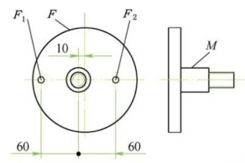
The flexible fixture, shown in Figure 9, is a welded frame structure with upper and lower support plates for mounting two pendulum blocks. The blocks are secured using bolts through their hinge holes. The fixture includes a central cavity for accessing bolts and adjustment handwheels. The right side has a locating hole (E1), and the left side has a corresponding hole (E2), aligned on the same axis. The right end piece features two eccentric center holes offset by 10mm, used for adjusting the fixture’s rotational center. The left end piece (Figure 11) includes a disc (F) and cylinder (M) with a 10mm eccentric offset, along with two locating holes (F1, F2) for positioning.
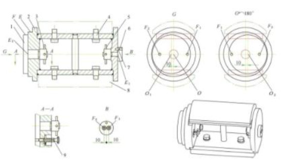
Operation of the Flexible Fixture
R140mm Arc Machining:
- Clamp two pendulum blocks onto the fixture’s support plates using hinge hole bolts.
- Secure the fixture’s outer circle (E) with a self-centering chuck, remove the right end piece, and position the tailstock center in the E1 hole.
- Rotate the fixture around the central axis (O) to machine the R140mm arc via turning.
Right R142mm Arc Machining:
- Remove the fixture from the lathe, insert the right end piece into the E1 hole, and secure it with a locating pin and handwheel.
- Insert a telescopic locating pin into the F1 hole on the left end piece and secure it, aligning the fixture’s rotational center (O1) with a 10mm left offset.
- Reinstall the fixture, clamp the outer circle (F), and position the tailstock center in the F1 hole to machine the right R142mm arc.
Left R142mm Arc Machining:
- Remove the fixture, release the handwheel, rotate the left end piece 180°, and insert the telescopic pin into the F2 hole to create a 10mm right offset (O2).
- Reinstall the fixture, clamp the outer circle (F), and position the tailstock center in the F2 hole to machine the left R142mm arc.
Workpiece Removal: Loosen the hinge hole bolts to remove the finished blocks.
Operational Recommendations
To enhance efficiency, two sets of fixtures can be used alternately. While one fixture is used to machine the R140mm arc, the second can be prepared for the R142mm arc, minimizing downtime for adjustments. This approach is particularly effective for medium-batch production.
Advantages and Limitations
| Advantages | Limitations |
|---|---|
| High surface finish (up to 1.6μm roughness) | Multiple setups increase auxiliary time |
| Cost-effective for small batches | Complex fixture adjustments |
| Simple tooling requirements | Requires skilled operators for setup |
| Adaptable to similar arc-shaped components |
The conventional lathe method offers superior surface quality and cost-effectiveness for small batches but requires multiple setups and skilled operation, which may reduce efficiency.
Comparison and Selection Criteria
Choosing between CNC turn-mill and conventional lathe depends on production requirements:
- Batch Size: CNC turn-mill is preferable for larger batches due to its automation and single-setup efficiency. Conventional lathes are better suited for small batches where equipment cost is a constraint.
- Surface Quality: Conventional lathes provide better surface finish (1.6μm) due to continuous turning, while CNC milling may introduce minor tool marks.
- Equipment Availability: Conventional lathes are more accessible in many workshops, while CNC turn-mill centers require significant investment.
- Operator Skill: CNC turn-mill requires programming expertise, whereas conventional lathes demand skilled fixture adjustments.
For high-precision, small-batch production with stringent surface finish requirements, the conventional lathe with a flexible fixture is optimal. For larger batches or workshops with advanced equipment, the CNC turn-mill center offers greater efficiency.
Conclusion
Both CNC turn-mill centers and conventional lathes with flexible fixtures can effectively machine multi-arc surface products like the pendulum block. The CNC approach excels in automation and setup simplicity but is limited by milling-related surface quality and efficiency issues. The conventional lathe method, enhanced by a flexible fixture, achieves superior surface finish and is cost-effective for small batches, though it requires more setup time. By understanding the specific requirements of batch size, surface quality, and equipment availability, manufacturers can select the most appropriate method to achieve high-quality results efficiently.