Turbine impellers are critical components in aerospace engines, responsible for energy transfer and thrust generation. Their complex geometry, high-performance materials, and demanding operating conditions necessitate stringent machining precision. This article provides a comprehensive overview of the precision requirements for machining turbine impellers, focusing on dimensional tolerances, surface finish, material considerations, and quality control processes. The content is structured to offer technical insights for engineers and manufacturers, emphasizing practical and systematic approaches to achieve aerospace-grade precision.
Overview of Turbine Impellers in Aerospace
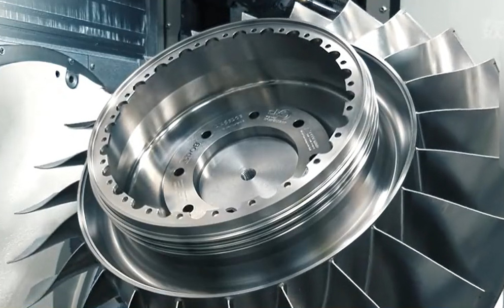
Turbine impellers, including blisks and radial impellers, are integral to aero-engines, converting kinetic energy into mechanical work. These components operate under extreme conditions, such as high temperatures (up to 1,500°C), pressures (exceeding 30 bar), and rotational speeds (often above 10,000 RPM). The impeller’s blades, hub, and flow passages must maintain precise geometries to ensure aerodynamic efficiency, structural integrity, and durability. Machining precision directly impacts engine performance, fuel efficiency, and safety, making it a non-negotiable aspect of aerospace manufacturing.
Common materials for impellers include titanium alloys (e.g., Ti-6Al-4V), nickel-based superalloys (e.g., Inconel 718), and forged aluminum alloys (e.g., ASTM B247-compliant). These materials are difficult to machine due to their high strength, low thermal conductivity, and tendency to work-harden. Precision machining, typically using 5-axis CNC machines, is employed to achieve the required tolerances and surface quality.
Dimensional Tolerances for Turbine Impellers
Dimensional tolerances define the acceptable limits for impeller geometry, ensuring proper fit, function, and performance. In aerospace applications, tolerances are exceptionally tight due to the impeller’s role in high-speed, high-stress environments. Key dimensional features include blade profile, hub diameter, central shaft hole, and blade-to-hub concentricity.
For large impellers (e.g., diameter ~430 mm), typical tolerances include:
- Central shaft hole concentricity: ±0.02 mm
- Blade profile relative to central channel: ±0.06 mm
- Blade thickness: ±0.05 mm
- Hub diameter: ±0.03 mm
Smaller impellers may require even tighter tolerances, such as ±0.01 mm for critical features. These tolerances are challenging for large components due to material deformation, tool wear, and thermal effects during machining. To address these, manufacturers use advanced 5-axis CNC machines with real-time feedback systems and rigid fixturing to minimize errors.
Blade profile accuracy is critical for aerodynamic performance. Deviations beyond ±0.05 mm can disrupt airflow, reducing efficiency by up to 2-3%. Coordinate Measuring Machines (CMMs) are used post-machining to verify tolerances, generating detailed inspection reports to ensure compliance with aerospace standards like AS9100.
Surface Finish Requirements
Surface finish affects the impeller’s aerodynamic efficiency, fatigue resistance, and wear performance. In aerospace, surface roughness is typically specified in terms of Ra (arithmetic average roughness) or Rz (maximum height of the profile). For turbine impellers, the required surface finish varies by component area:
| Component Area | Surface Roughness (Ra) | Purpose |
|---|---|---|
| Blade surfaces | 0.8–1.6 µm | Minimize airflow turbulence, reduce drag |
| Hub surfaces | 1.6–3.2 µm | Ensure structural integrity, support coating adhesion |
| Flow passages | 0.8–1.2 µm | Optimize fluid dynamics, prevent cavitation |
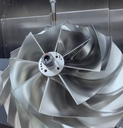
Achieving these finishes requires advanced machining strategies, such as high-speed 5-axis milling with ball-end mills and climb-cutting techniques. For example, a spindle speed of 20,000–30,000 RPM and a low feed rate (0.1–0.3 mm/rev) are often used to ensure smooth blade surfaces. Post-machining processes like abrasive flow machining or polishing may be applied to refine surfaces, particularly in flow passages.
Surface integrity is equally important. Microcracks, residual stresses, or recast layers from improper machining can reduce fatigue life by 20-30%. Techniques like laser peening or wet shot peening are sometimes used to enhance surface compressive stresses, improving durability.
Material Considerations in Machining
The choice of material for turbine impellers is driven by operating conditions, weight requirements, and durability. Common materials and their machining challenges are summarized below:
| Material | Properties | Machining Challenges |
|---|---|---|
| Titanium Alloys (e.g., Ti-6Al-4V) | High strength-to-weight ratio, corrosion resistance | Low thermal conductivity, high tool wear, work-hardening |
| Nickel-Based Superalloys (e.g., Inconel 718) | High-temperature strength, creep resistance | High hardness, abrasive chips, built-up edge formation |
| Forged Aluminum Alloys | Lightweight, good machinability | Thermal distortion, burr formation |
Machining these materials requires specialized tools, such as carbide or ceramic inserts, and optimized parameters. For titanium, cutting speeds of 30–60 m/min and coolant application are standard to manage heat. For superalloys, slower speeds (20–40 m/min) and high-pressure coolant (70–100 bar) reduce tool wear. Tool life monitoring systems are critical to prevent defects and ensure consistent precision.
Material defects, such as inclusions or voids, can compromise impeller performance. Non-destructive testing (NDT), including ultrasonic and X-ray inspection, is performed on raw materials to ensure homogeneity. For large impellers, the high cost of raw material blanks (e.g., $5,000–$10,000 per blank) necessitates rigorous inspection to avoid machining losses.
Machining Processes for Turbine Impellers
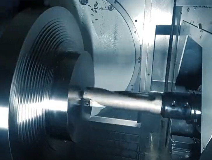
The machining of turbine impellers typically involves multiple stages: roughing, semi-finishing, and finishing. Each stage has distinct precision requirements and employs specific techniques:
- Roughing: Removes bulk material (up to 80% for solid blanks) using high-feed milling. Tolerances are relaxed (±0.2 mm), prioritizing material removal rate. Tools include large-diameter end mills with robust geometries.
- Semi-Finishing: Refines geometry to within ±0.1 mm of final dimensions. Flank milling or point milling is used, depending on blade complexity. CAM software optimizes tool paths to minimize vibration.
- Finishing: Achieves final tolerances and surface finish. 5-axis point milling with ball-end mills ensures profile accuracy (±0.05 mm). High-speed spindles and low feed rates are critical.
Advanced 5-axis CNC machines, such as those from DMG Mori, are standard for impeller machining. These machines offer multi-axis control, real-time data monitoring, and automation to maintain precision. CAM software like MAX-PAC is used to generate optimal tool paths, reducing machining time by 10-15% while ensuring accuracy.
Alternative processes, such as electrochemical machining (ECM) or wire-EDM, are occasionally used for specific features. However, their limitations (e.g., recast layers in EDM) restrict their use to roughing or niche applications.
Quality Control and Inspection
Quality control is integral to impeller manufacturing, ensuring compliance with aerospace standards. Inspection occurs at multiple stages: raw material, in-process, and final product. Key methods include:
- CMM Inspection: Measures dimensional tolerances with accuracy up to ±0.002 mm. CMMs generate 3D point clouds to verify blade profiles and hub geometry.
- Optical Measurement: Assesses surface finish and coating uniformity using high-resolution imaging. Systems like ZEISS microscopy ensure Ra values meet specifications.
- Non-Destructive Testing (NDT): Detects internal defects using ultrasonic, X-ray, or CT scanning. NDT is critical for high-value components to prevent in-service failures.
- Balance Verification: Ensures dynamic balance to minimize vibrations. Material may be selectively removed to achieve balance within ±0.1 g·mm.
Inspection data is documented per AS9102 standards, providing traceability for regulatory compliance. Real-time feedback systems allow process adjustments during machining, reducing rejection rates to below 1%. For critical impellers, 100% inspection is standard to ensure zero defects.
Practical Considerations for Manufacturers
Achieving the required precision for turbine impellers demands a systematic approach. Manufacturers must consider:
- Equipment Investment: High-precision 5-axis CNC machines and CMMs are costly (e.g., $500,000–$2 million per machine) but essential for aerospace-grade quality.
- Tool Management: Regular tool inspection and replacement prevent defects. Tool life for superalloys may be as low as 30–60 minutes, requiring robust inventory systems.
- Operator Expertise: Skilled programmers and machinists are critical for optimizing CAM software and machine parameters. Training programs enhance consistency.
- Process Optimization: Rational allowance distribution and checkpoint inspections during machining minimize rework. Process parameters are adjusted based on material and geometry.
Collaboration with customers is vital to align machining processes with design specifications. Manufacturers often refine impeller designs to improve machinability, reducing production time by 5-10% without compromising performance.
Conclusion
Machining turbine impellers for aerospace applications requires exceptional precision to meet stringent dimensional, surface, and material requirements. Advanced 5-axis CNC machining, coupled with rigorous quality control, ensures compliance with aerospace standards. By understanding tolerances, surface finish needs, material challenges, and inspection protocols, manufacturers can produce reliable, high-performance impellers. This systematic approach, grounded in technical expertise, supports the safety and efficiency of modern aero-engines, reinforcing the critical role of precision machining in aerospace manufacturing.