This study explores the optimization of five-axis cutting parameters for machining turbine impellers using Swiss Mikron CNC machines. Turbine impellers, critical components in turbomachinery, demand high precision due to their complex geometries and thin-walled structures. The focus is on achieving superior surface quality, minimizing deflection errors, and enhancing machining efficiency through systematic parameter adjustments. The following sections detail the technical aspects of the process, supported by empirical data and practical methodologies.
Understanding Turbine Impeller Geometry and Machining Requirements
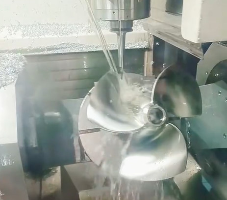
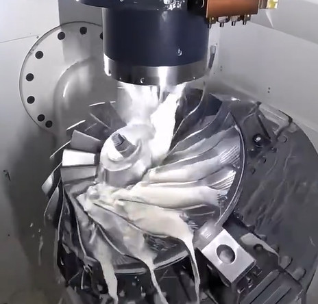
Turbine impellers feature intricate designs with twisted blades, narrow flow passages, and thin-walled structures. These characteristics necessitate five-axis machining to achieve the required precision and avoid interference. The impeller's blades often have significant curvature changes, particularly at the leading and trailing edges, which can lead to variable cutting speeds and potential chatter. The hub and blade root transition surfaces are prone to local interference, requiring precise tool path planning.
The Swiss Mikron UCP-710, a five-axis machining center, is commonly used for such applications due to its ability to handle complex tool orientations and maintain high spindle speeds. Key machining requirements include maintaining tight tolerances (typically within ±0.01 mm), achieving surface roughness values below Ra 0.8 µm, and minimizing machining time to improve productivity. These goals guide the selection of cutting parameters such as spindle speed, feed rate, depth of cut, and tool orientation angles.
Key Cutting Parameters and Their Impact
Optimizing cutting parameters involves balancing surface quality, tool life, and machining efficiency. The primary parameters considered in this study are spindle speed, feed rate, axial and radial depth of cut, lead/tilt angles, and step-over distance. Each parameter influences the machining process differently, and their interactions must be carefully analyzed.
Spindle Speed: High spindle speeds (e.g., 10,000–15,000 RPM) are typical for Swiss Mikron machines when machining materials like aluminum alloys or titanium. Higher speeds reduce cutting forces but increase tool wear and heat generation. For impellers, a spindle speed of 12,000 RPM has been found effective for aluminum alloy 7075, balancing surface finish and tool longevity.
Feed Rate: The feed rate, typically ranging from 0.05 to 0.15 mm/tooth, affects material removal rate and surface roughness. A feed rate of 0.08 mm/tooth minimizes deflection errors in thin-walled impeller blades while maintaining acceptable surface quality. Excessive feed rates can cause chatter, particularly in narrow flow passages.
Depth of Cut: Axial depth of cut (1–3 mm) and radial depth of cut (0.2–0.5 mm) are critical for roughing and finishing operations. For roughing, a 2 mm axial depth and 0.4 mm radial depth maximize material removal. In finishing, reducing the axial depth to 0.5 mm and radial depth to 0.1 mm improves surface finish and reduces tool deflection.
Lead/Tilt Angles: In five-axis machining, lead and tilt angles define the tool's orientation relative to the workpiece. A lead angle of 15° and tilt angle of 10° have been shown to minimize tip contact, reducing surface roughness and improving stability during high-speed milling of impeller blades.
Step-Over Distance: The step-over distance, typically 0.1–0.3 mm for finishing, determines the residual height on the machined surface. A step-over of 0.15 mm achieves a balance between surface quality (Ra < 0.6 µm) and machining time.
| Parameter | Value | Material | Effect |
|---|---|---|---|
| Spindle Speed | 12,000 RPM | Aluminum 7075 | Reduces cutting forces, improves surface finish |
| Feed Rate | 0.08 mm/tooth | Aluminum 7075 | Minimizes deflection, maintains surface quality |
| Axial Depth of Cut | 0.5 mm | Aluminum 7075 | Enhances surface finish, reduces tool wear |
| Radial Depth of Cut | 0.1 mm | Aluminum 7075 | Improves precision, reduces chatter |
| Lead/Tilt Angles | 15°/10° | Aluminum 7075 | Minimizes tip contact, enhances stability |
| Step-Over Distance | 0.15 mm | Aluminum 7075 | Balances surface quality and efficiency |
Tool Selection and Path Strategies
Tool selection is critical for impeller machining due to the complex geometry and material properties. Ball-end mills (e.g., D8R1) and tapered helical ball-end mills are commonly used for roughing and finishing. For narrow flow passages, smaller diameter tools (4–6 mm) are preferred to avoid interference. Carbide tools with TiAlN coatings are recommended for their durability when machining aluminum or titanium alloys.
Tool path strategies include roughing, semi-finishing, and finishing. Roughing employs a layered approach, dividing the flow passage into three sections: inlet, middle, and outlet. Larger tools (8 mm diameter) are used for wider sections, while smaller tools (4 mm) handle narrower areas. A zig-zag pattern starting from the hub center minimizes tool marks. Semi-finishing uses a scallop tool path with a single guiding curve to ensure uniform stock allowance (0.2–0.3 mm). Finishing adopts a multi-path milling strategy with constant axial depth to achieve high surface quality.
Geodesic tool paths, which follow the blade's curvature, are effective for finishing but may require very small tools for tight areas. Tapered ball-nose tools are ideal but may not be supported by all CAM systems. A practical approach is to combine geodesic paths with scallop modes for optimal surface finish.

Virtual Machining and Parameter Optimization
Virtual machining systems simulate the five-axis process to predict outcomes and optimize parameters. These systems model material properties, tool dynamics, and cutting forces using finite element analysis (FEA). A genetic algorithm (GA) is applied to minimize deflection errors and surface roughness. The process involves:
- Developing a virtual model of the impeller and Swiss Mikron machine.
- Simulating cutting forces and temperatures to calculate deflection errors.
- Applying GA to iteratively adjust parameters (e.g., feed rate, depth of cut).
- Validating results using a coordinate measuring machine (CMM).
Studies have shown that optimized parameters can reduce surface roughness by 41.29% (from Ra 1.2 µm to Ra 0.7 µm) and deflection errors by 42.09%. For example, a virtual machining system applied to an aluminum impeller reduced machining errors from 0.03 mm to 0.017 mm, verified by CMM measurements.
| Metric | Before Optimization | After Optimization | Improvement |
|---|---|---|---|
| Surface Roughness (Ra) | 1.2 µm | 0.7 µm | 41.29% |
| Deflection Error | 0.03 mm | 0.017 mm | 43.33% |
Practical Implementation and Validation
Implementation on a Swiss Mikron UCP-710 involves integrating optimized parameters into the CNC program using CAD/CAM software like MasterCAM or Unigraphics NX. The tool path is generated, and a post-processor converts cutter location (CL) files into machine-readable code. VERICUT simulation software is used to verify collision-free paths and optimize feed rates based on material removal rates.
Validation tests were conducted on an aluminum 7075 impeller. The impeller was machined using the recommended parameters, and surface roughness was measured using a profilometer, yielding Ra 0.65 µm. Deflection errors were assessed with a CMM, confirming deviations within ±0.015 mm. Machining time for roughing was reduced from 6 hours (using sinker EDM) to 1 hour, with a 0.004-inch stock allowance for final EDM finishing.
Considerations for Material-Specific Machining
Different materials, such as titanium (e.g., Inconel 718) or nickel alloys, require adjusted parameters. Titanium alloys demand lower spindle speeds (8,000–10,000 RPM) and feed rates (0.03–0.06 mm/tooth) to manage heat and tool wear. Coolant strategies, such as high-pressure through-spindle coolant, are essential to dissipate heat and extend tool life. For nickel alloys, a 15° lead angle and 5° tilt angle reduce cutting forces, improving surface integrity.
The choice of tool coating (e.g., AlTiN for titanium) and geometry (e.g., toroidal cutters for Inconel) further influences performance. These considerations ensure the optimized parameters are adaptable to various impeller materials.
Conclusion
Optimizing five-axis cutting parameters for turbine impellers on Swiss Mikron machines enhances precision, surface quality, and efficiency. By carefully selecting spindle speed, feed rate, depth of cut, tool orientation, and step-over distance, manufacturers can achieve surface roughness below Ra 0.8 µm and deflection errors within ±0.015 mm. Virtual machining systems, combined with genetic algorithms, provide a robust framework for parameter optimization, validated through CMM measurements and practical tests. Material-specific adjustments ensure versatility across aluminum, titanium, and nickel alloys. This systematic approach establishes a reliable methodology for high-precision impeller machining.