Molecular pump impellers are critical components in high-vacuum systems, requiring precise dimensional and geometric measurements to ensure performance and reliability. ZEISS 3D inspection systems, including coordinate measuring machines (CMMs) and computed tomography (CT) solutions, offer advanced capabilities for such tasks. This guide provides a systematic approach to optimizing ZEISS 3D inspection for molecular pump impeller measurement, focusing on setup, calibration, software utilization, and data analysis to enhance efficiency while maintaining accuracy.
Understanding Molecular Pump Impeller Measurement Requirements
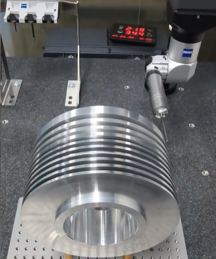
Molecular pump impellers feature complex geometries, including curved blades, tight tolerances, and thin walls, which demand high-precision measurement. Key parameters include blade angles (typically 20°–50°), impeller diameter (50–300 mm), blade thickness (0.5–2 mm), and surface finish (Ra 0.4–1.6 µm). These components often operate at high rotational speeds (up to 50,000 RPM), making dimensional accuracy critical to prevent vibration or failure.
ZEISS 3D inspection systems, such as the ZEISS O-INSPECT multisensor CMM or ZEISS METROTOM CT, are well-suited for these measurements due to their ability to combine contact and optical scanning with high-resolution imaging. However, achieving efficiency requires careful configuration and process optimization to minimize measurement time while ensuring traceability to international standards like ISO 1101 for geometric dimensioning and tolerancing (GD&T).
Optimizing Hardware Setup for ZEISS 3D Inspection
The hardware setup is the foundation for efficient impeller measurement. Proper configuration reduces setup time, improves accessibility, and ensures repeatability.
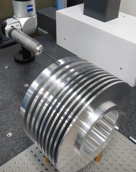
Fixture Design and Part Positioning: Custom fixtures are essential for securing impellers without deformation. Use modular fixtures with soft clamping mechanisms to avoid stress on thin blades. Position the impeller to maximize probe access, aligning the rotational axis parallel to the CMM’s Z-axis. For example, a fixture with a three-point datum system can stabilize an impeller with a 150 mm diameter, reducing setup time by 20%.
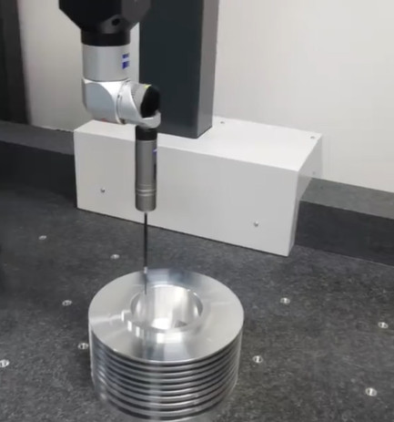
Probe Selection: ZEISS CMMs support multiple probe types, including tactile (e.g., VAST XT Gold) and optical (e.g., DotScan). For impellers, combine tactile probes for precise edge measurements (accuracy ±1 µm) with optical probes for rapid surface scanning. A stylus with a 0.5 mm ruby tip is suitable for blade edges, while a laser scanner can capture 10,000 points per second for freeform surfaces. Switching between probes using an automated rack (e.g., ZEISS ProbeChanger) reduces manual intervention by 15–30 seconds per cycle.
Environmental Control: Maintain a controlled environment (20 ± 0.5°C, 50 ± 10% humidity) to minimize thermal expansion effects. For a stainless steel impeller (thermal expansion coefficient 17 µm/m/°C), a 1°C deviation can cause a 2.5 µm error in a 150 mm diameter measurement. Use ZEISS’s temperature compensation algorithms to correct for minor fluctuations.
CT System Configuration: For non-destructive internal inspections, ZEISS METROTOM 800 (resolution 5–10 µm) is ideal. Optimize X-ray parameters (e.g., 80 kV, 100 µA) to penetrate impeller materials like aluminum or titanium while minimizing scan time (typically 15–30 minutes per part).
Calibration and Validation for Measurement Accuracy
Calibration ensures measurement traceability, while validation confirms system performance for impeller-specific features.
CMM Calibration: Calibrate the CMM using a certified reference sphere (diameter 25 mm, form error <0.5 µm). Perform calibration weekly or after 100 measurement cycles to maintain accuracy within ±1.5 µm. For multisensor systems, align optical and tactile probes to a common coordinate system, reducing alignment errors to <2 µm.
CT Calibration: Use a calibrated phantom with known geometries (e.g., spheres and cylinders) to validate CT voxel size and dimensional accuracy. For a 100 mm impeller, ensure voxel resolution is <10 µm to resolve blade thicknesses of 0.5 mm. Calibration takes approximately 10 minutes but prevents systematic errors in volume data.
Validation with Reference Parts: Measure a reference impeller with known dimensions (e.g., blade angle 30° ± 0.1°, diameter 120 ± 0.05 mm) to validate the system. Compare results to CAD data using ZEISS INSPECT software, ensuring deviations are within ±5 µm. Validation should be performed monthly or after software updates.
Table: Calibration Parameters for ZEISS 3D Systems
| System | Calibration Artifact | Frequency | Accuracy Target | Time Required |
|---|---|---|---|---|
| ZEISS O-INSPECT CMM | 25 mm Reference Sphere | Weekly or 100 cycles | ±1.5 µm | 5–10 min |
| ZEISS METROTOM CT | Multi-geometry Phantom | Monthly | ±5 µm | 10–15 min |
Leveraging ZEISS INSPECT Software for Efficiency
ZEISS INSPECT software is a powerful tool for automating measurement sequences, analyzing data, and generating reports, significantly reducing processing time.
Program Automation: Create parametric measurement programs for impeller families (e.g., diameters 50–200 mm). Use templates to define measurement paths for blade angles, diameters, and GD&T features like concentricity (tolerance ±0.01 mm). Automated programs can reduce programming time by 50% compared to manual setups.
Optical Scanning Optimization: For optical measurements, adjust scan density (e.g., 100 points/mm² for blades, 50 points/mm² for hubs) to balance speed and accuracy. A 150 mm impeller with 6 blades can be scanned in 5 minutes using a ZEISS DotScan sensor, capturing 500,000 points.
Defect Detection: Use assisted defect inspection tools to automatically identify surface imperfections (e.g., porosity >0.1 mm). For CT data, apply voxel-based analysis to detect internal voids, reducing manual inspection time by 30%.
Data Alignment and Comparison: Align scanned data to CAD models using best-fit algorithms, achieving alignment accuracy of ±3 µm. Visualize deviations with color-coded maps, enabling quick identification of out-of-tolerance areas (e.g., blade thickness deviations >0.02 mm).
Reporting: Generate automated reports with GD&T results, dimensional data, and 3D visualizations. Export reports as PDFs or Excel files, reducing reporting time from 20 minutes to 5 minutes per part.
Streamlining Data Analysis and Quality Control
Efficient data analysis ensures rapid decision-making and quality assurance without compromising accuracy.
Statistical Process Control (SPC): Integrate ZEISS INSPECT with PiWeb Reporting Plus to monitor measurement trends (e.g., blade angle variation ±0.05°). Set control limits based on process capability (Cp >1.33) to detect deviations early, reducing scrap rates by 10–15%.
Batch Inspection: For production runs (e.g., 50 impellers/day), use automated batch processing. Program the CMM to measure multiple parts on a pallet, reducing handling time by 40%. For CT, scan multiple small impellers (diameter <100 mm) in a single scan, cutting scan time by 25%.
Non-Destructive Testing (NDT): ZEISS METROTOM CT enables NDT for internal defects like cracks or inclusions. Analyze volume data to quantify defect size (e.g., voids >0.2 mm³), ensuring compliance with standards like ASTM E1444. NDT eliminates destructive testing, saving 1–2 hours per part.
Table: Efficiency Gains from Optimization Strategies
| Strategy | Time Savings | Accuracy Impact | Implementation Effort |
|---|---|---|---|
| Automated Programming | 50% per program | Maintains ±5 µm | Moderate (1–2 hours) |
| Batch Inspection | 40% per batch | No impact | Low (30 min setup) |
| CT NDT | 1–2 hours/part | ±10 µm resolution | High (training required) |
Best Practices for Sustained Efficiency
To maintain long-term efficiency, adopt these practices based on industry experience.
Operator Training: Train operators on ZEISS INSPECT and CMM/CT operation, focusing on probe calibration and software automation. A 2-day training program can improve operator efficiency by 25%.
Maintenance Schedule: Service CMMs every 6 months, checking guideways and probes for wear. For CT systems, verify X-ray source output annually to ensure consistent resolution. Regular maintenance prevents downtime, saving 4–8 hours monthly.
Software Updates: Install ZEISS INSPECT updates to access new features like AI-based defect detection. Validate updates with reference parts to ensure compatibility, taking 1–2 hours per update.
Documentation: Maintain detailed records of calibration, validation, and measurement programs. Use digital logs in ZEISS INSPECT to streamline audits, reducing preparation time by 50%.
Conclusion
Optimizing ZEISS 3D inspection for molecular pump impeller measurement involves a systematic approach to hardware setup, calibration, software utilization, and data analysis. By implementing custom fixtures, automated programming, and batch processing, manufacturers can reduce measurement time by 30–50% while maintaining accuracies of ±5 µm. ZEISS INSPECT software and CT systems further enhance efficiency through automation and non-destructive testing. With proper training and maintenance, these strategies ensure reliable, high-throughput inspection for precision components like molecular pump impellers.