Planar machining is a cornerstone of mechanical manufacturing, essential for producing flat surfaces on workpieces with the required shape, size, dimensional accuracy, and surface finish. This process encompasses a range of operations, from initial material removal to final precision finishing. The selection of a specific method depends on numerous factors, including the workpiece material, desired surface quality, production volume, and cost constraints. This guide provides a detailed and technical exploration of the primary methods and types of planar machining, examining their operational principles, characteristics, and practical applications.
Primary Planar Machining Methods: Principles and Technical Specifications
Each planar machining method employs distinct tools and kinematics to remove material, resulting in unique process capabilities and limitations. A thorough understanding of these principles is critical for effective process planning and achieving desired part specifications.
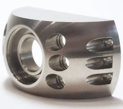
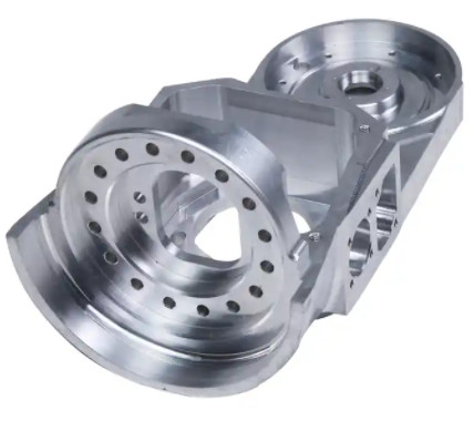
1. Milling
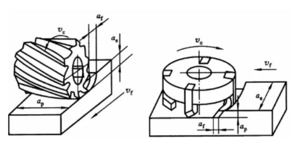
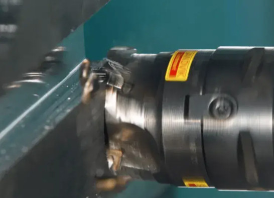
Milling is arguably the most versatile and widely used method for planar machining. It utilizes a rotating multi-point cutter to remove material from a workpiece. The process can be classified into two main types for flat surface generation: face milling and peripheral milling. Face milling uses a cutter with teeth on its face and periphery, with the cutter axis perpendicular to the machined surface. Peripheral milling, in contrast, uses a cylindrical cutter with teeth on its circumference, with the cutter axis parallel to the machined surface.
The primary cutting motion in milling is the rotation of the cutter, while the feed motion is the linear movement of the workpiece or cutter. The intermittent cutting action, where each tooth takes a chip in sequence, and the high spindle speeds allow for high material removal rates. Modern CNC milling machines have significantly enhanced the precision and automation of this process, making it suitable for a wide range of materials and complex geometries. Key technical considerations in milling include cutter selection (e.g., face mills, end mills, slab mills), cutting parameters (feed rate, cutting speed, depth of cut), and tool path strategies.
2. Planing
Planing is a fundamental single-point cutting process primarily used for machining large, flat surfaces. It involves a single-point tool, or planer tool, mounted on a ram that moves back and forth in a linear, reciprocating motion across a stationary workpiece. The primary cutting motion is the forward stroke of the ram, during which material is removed. The return stroke is non-cutting, which contributes to its relatively lower efficiency compared to milling.
Due to the simple tool geometry and machine structure, planing is highly adaptable and commonly employed for low-volume production, especially for elongated or narrow flat surfaces where other methods may be less practical. While the kinematics of planing limit the cutting speed and overall productivity, its simplicity makes it an economical choice for specific applications. Modern planing machines often have adjustable strokes and feed rates, providing a degree of control over the process.
3. Grinding
Grinding is a highly precise finishing operation that uses an abrasive wheel to remove very small amounts of material from a workpiece. The abrasive grains on the wheel act as cutting points, capable of achieving exceptional dimensional accuracy and superior surface finishes. The kinematics of grinding involve the high-speed rotation of the grinding wheel and controlled feed movements of the workpiece. The process generates a large amount of heat, necessitating the use of cutting fluids to cool the workpiece and prevent thermal damage.
Grinding is categorized by the geometry of the workpiece being ground. For planar machining, common types include surface grinding, which can be performed on both horizontal and vertical spindle machines. Surface grinding is the final stage for achieving high-precision surfaces, often used on hardened materials or to achieve micro-level surface roughness. Technical aspects include selecting the correct abrasive grain, wheel bond, and grit size, as well as managing coolant flow and dressing the wheel to maintain its cutting efficiency.
4. Broaching
Broaching is a highly productive machining process that uses a multi-tooth tool, known as a broach, to cut a specific shape in a single pass. Each successive tooth on the broach is slightly taller than the one before it, ensuring that the full depth of cut is achieved as the tool is pulled or pushed through the workpiece. For planar machining, broaching is used to create flat surfaces, keyways, or other complex profiles on large batches of parts.
The primary motion in broaching is the linear movement of the broach tool relative to the workpiece. Because the entire cutting process is completed in one stroke, broaching is exceptionally fast and efficient for high-volume production. It is a highly specialized process, as a unique broach tool is required for each specific part and shape. This high initial tooling cost is offset by the extremely high production rate and excellent surface quality achieved. It is particularly well-suited for internal surfaces, such as the bores of engine blocks and gear housings.
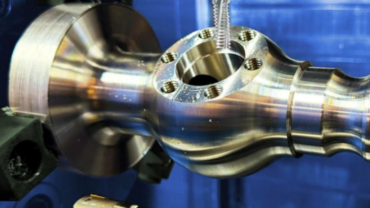
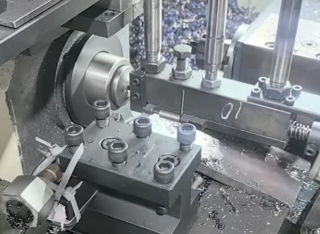
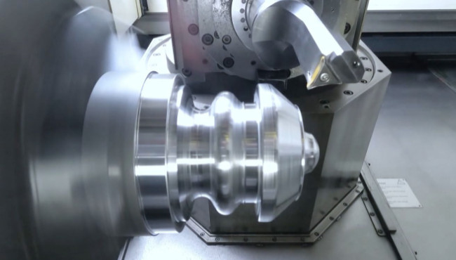
5. Turning
While turning is primarily used for generating cylindrical surfaces, it can also be used for planar machining of end faces. This specific application is known as facing. During facing, the workpiece rotates on the lathe spindle, and a single-point cutting tool is fed radially across the end face of the workpiece. This motion generates a flat surface perpendicular to the axis of rotation.
Facing is ideal for machining simple end faces on rotational parts. The process is relatively straightforward, but careful control of the feed rate and tool geometry is required to achieve a flat surface with a good finish. It is often performed in conjunction with other turning operations to complete a part in a single setup. The versatility of a lathe makes it a viable option for machining simple planar surfaces on rotational components.
Types of Planar Machining: Operations and Surface Quality
The overall machining process for a single workpiece is typically divided into a series of operations to systematically achieve the final required geometry and surface finish. These operational types are defined by the amount of material removed, the dimensional tolerance, and the surface roughness requirements.
1. Roughing Operations
Roughing is the initial stage of machining, with the primary objective of removing the bulk of the excess material from the workpiece as quickly and efficiently as possible. This stage prepares the workpiece for subsequent operations by bringing it close to its final dimensions. The key characteristics of roughing include high material removal rates (MRR), large depths of cut, and relatively high feed rates. Dimensional tolerances and surface finish are secondary considerations at this stage. Common methods for roughing planar surfaces include milling and planing due to their capacity for aggressive material removal.
2. Semi-Finishing Operations
Semi-finishing is an intermediate stage between roughing and finishing. Its purpose is to further reduce the amount of excess material left on the workpiece and improve the dimensional accuracy and surface quality achieved during roughing. This stage ensures that the final finishing operation has a consistent and manageable amount of material to remove, which improves the precision and tool life of the finishing tools. Like roughing, semi-finishing for flat surfaces often employs milling or planing, but with more conservative cutting parameters to achieve better control over the final geometry.
3. Finishing Operations
Finishing is the final machining stage, focused on achieving the precise dimensional tolerances and high-quality surface finish specified for the part. During this operation, only a minimal amount of material is removed. The cutting parameters—including feed rate and depth of cut—are very small to minimize tool marks and surface imperfections. Grinding is the most common method for finishing planar surfaces due to its ability to achieve exceptionally tight tolerances and smooth surfaces. Other finishing methods may include fine milling or superfinishing processes, depending on the specific surface finish requirements.
Comparative Analysis of Planar Machining Methods
Selecting the optimal planar machining method requires a careful trade-off analysis based on a variety of technical and economic factors. The following table provides a comparative overview of the key characteristics of each method.
| Method | Material Removal Rate (MRR) | Typical Application | Process Complexity | Surface Roughness (Ra) |
|---|---|---|---|---|
| Milling | High (Roughing to Finishing) | Medium- to High-Volume Production | Medium to High | 0.8 - 6.3 µm |
| Planing | Medium to High (Roughing) | Low-Volume, Large Workpiece Production | Low | 1.6 - 12.5 µm |
| Grinding | Very Low (Finishing) | High-Precision Finishing, Hardened Materials | Medium to High | 0.1 - 0.8 µm |
| Broaching | Very High (Finishing) | High-Volume Production | High (Tooling) | 0.8 - 3.2 µm |
| Turning (Facing) | Medium | Machining End Faces on Rotational Parts | Medium | 0.8 - 6.3 µm |
The choice of method is also heavily influenced by the desired surface finish, which is often a critical engineering specification. The table below details the typical surface roughness values achievable with each method.
| Surface Roughness (Ra) Range | Typical Machining Method | Comment |
|---|---|---|
| 12.5 µm to 6.3 µm | Planing (Roughing) | Initial material removal, large feed rates and depth of cut. |
| 6.3 µm to 1.6 µm | Milling (Semi-Finishing) | Standard machining for general purpose surfaces. |
| 1.6 µm to 0.8 µm | Broaching, Turning, Milling (Finishing) | Suitable for surfaces requiring good fit and function. |
| 0.8 µm to 0.1 µm | Grinding (Finishing) | Required for precision components, bearing surfaces, and optics. |
Considerations and Constraints in Planar Machining
While the choice of method is primarily driven by technical requirements, several practical considerations and limitations can influence the final decision. These factors are crucial for ensuring a manufacturable and cost-effective process.
- Workpiece Material: The machinability of the material dictates the choice of cutting tools, cutting speeds, and feed rates. Hardened steels, for example, are typically ground, while aluminum alloys can be milled at high speeds.
- Dimensional Accuracy and Tolerances: The required precision of the final part is a major determinant. For surfaces with tolerances in the micrometer range, grinding is often the only viable option.
- Production Volume: For single-part or low-volume runs, the low setup cost of planing or simple milling may be preferred. In contrast, high-volume production justifies the high tooling costs of broaching, which can then yield significant per-part cost savings due to its high efficiency.
- Machine Rigidity and Power: The chosen machine tool must have sufficient rigidity to withstand cutting forces without deflection, especially during heavy roughing cuts.
- Tooling and Fixturing: The complexity and cost of designing and manufacturing custom tooling and fixtures can be a significant factor. Broaching, for instance, requires a dedicated, expensive tool for each part geometry.
- Surface Integrity: Machining processes can induce residual stresses or heat-affected zones in the workpiece material. Grinding, in particular, must be carefully controlled to avoid surface burns or microcracks.
- Part Geometry and Size: The physical dimensions and shape of the workpiece can limit the available machining options. Large, heavy plates may be suited for planing, while small, intricate parts may require a high-speed milling center.
Conclusion
Planar machining is a diverse field of manufacturing, with a variety of methods available to achieve a flat surface. Each method—be it milling, planing, grinding, broaching, or turning—has a unique set of technical characteristics, advantages, and limitations. The selection of the most appropriate method is a multi-faceted engineering decision that balances the technical requirements of the part with the economic realities of production. As manufacturing technology continues to advance, the efficiency, precision, and automation of these processes will only continue to improve, providing engineers with an ever-expanding toolkit for producing high-quality components.