
Gears are fundamental components in mechanical transmission systems, with extensive applications in automotive, agricultural machinery, and industrial equipment. They are classified into vehicle gears, general industrial gears, and specialized industrial gears. Vehicle gears encompass those for automobiles, motorcycles, agricultural vehicles, and construction machinery. General industrial gears include cylindrical gear transmissions and cylindrical-conical gear reducers, while specialized industrial gears cover high-speed gears, marine gears, and gears for petrochemical and construction machinery. In 2017, high-end, mid-range, and low-end gears represented approximately 25%, 35%, and 40% of the market, respectively. Enterprises producing these gears were distributed as 15% for high-end, 30% for mid-range, and 55% for low-end products. That year, China's gear imports reached approximately $16 billion, with growing demand for high-precision gears, particularly for automotive automatic transmissions and robotic precision reducers, which continue to rely heavily on imports.
Traditional Gear Machining Methods
Traditional gear machining processes include hobbing, shaping, grinding, and milling, each suited to specific gear types and applications. Hobbing, for example, relies on customized hobs for high-volume production but is less cost-effective for small-batch, multi-variety production due to the high cost of custom hobs. Leading global manufacturers, such as Gleason (USA), Pfauter (Germany), WERA (Germany), Nachi-Fujikoshi (Japan), and Reishauer (Switzerland), dominate the high-end gear market. The industry’s shift toward multi-variety, small-batch production has increased the use of universal five-axis CNC machines, which offer greater flexibility compared to traditional methods.
Curved Gear Structure and Technical Specifications
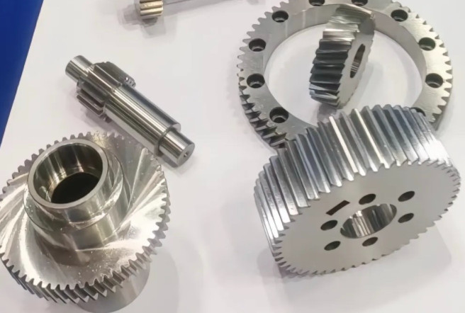
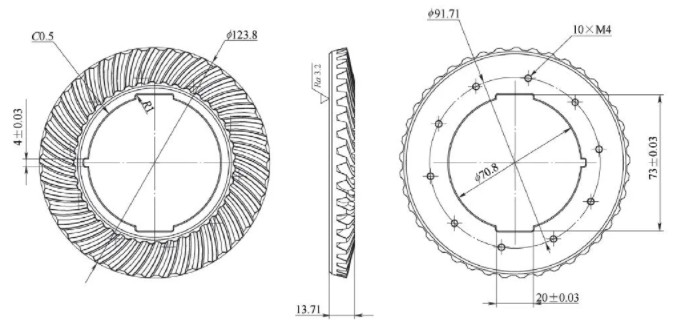
Curved gears, used in applications like high-frequency tool-changing mechanisms, demand precise machining to ensure durability and performance. For instance, a tool-changing mechanism sourced from an overseas manufacturer failed after approximately 30,000 tool changes. Using Beijing Jingdiao’s five-axis CNC equipment, a curved gear was machined, achieving over 100,000 tool changes without failure. The gear structure includes small and large curved gears, each with specific technical parameters critical to their performance.
| Parameter | Small Curved Gear | Large Curved Gear |
|---|---|---|
| Module | 2.5 | 2.5 |
| Number of Teeth | 24 | 48 |
| Pressure Angle (°) | 20 | 20 |
| Helix Angle (°) | 15 | 15 |
| Face Width (mm) | 20 | 25 |
| Material | 38CrMoAl | 38CrMoAl |
Fixture Design for Curved Gear Machining
Effective fixture design is critical for precision gear machining. The fixture achieves a flatness tolerance of ≤0.003 mm and employs bolt clamping to secure the workpiece. Positioning the workpiece at the machine’s axis center, with the spindle lowered to an optimal height, ensures stability and accessibility during machining. This configuration minimizes vibrations and maintains consistent machining accuracy across gear surfaces.
Programming with JDSoft SurfMill Software
JDSoft SurfMill, a CAM software developed by Beijing Jingdiao, is optimized for gear machining. It uses the generating method, aligned with traditional gear machining, to compute tool paths. The software streamlines programming, improves operational efficiency, and delivers high path calculation accuracy. Integrated Digital Twin (DT) technology enables visualized programming, while in-machine measurement ensures machining safety. The generating method simulates gear meshing, using the tool’s side edge to cut along the gear surface’s tangential direction, progressively forming the gear profile. Users can configure toolpath strategies, cutting sequences, and generating parameters within the software’s interface, with simulation results validating toolpath accuracy prior to machining.
Tool Selection: Tapered Bullnose End Mill
The tapered bullnose end mill is selected for machining curved gears due to its balance of rigidity and accessibility. Its tapered geometry enables precise cutting of complex gear profiles, particularly in tight spaces like gear roots, while maintaining surface quality. The table below compares the tapered bullnose end mill with other tool types.
| Tool Type | Advantages | Disadvantages |
|---|---|---|
| Tapered Bullnose End Mill | High precision, suitable for complex profiles, good surface finish | Higher cost, requires precise programming |
| Flat End Mill | Cost-effective, widely available | Limited access to complex geometries, poorer surface finish |
| Ball End Mill | Good for curved surfaces, versatile | Lower material removal rate, less rigid |
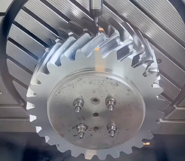
Machining Process and Workflow
The machining process for curved gears involves multiple stages to achieve the required precision and surface quality. The workflow includes:
- Rough Machining: A large-diameter tapered bullnose end mill, matching the gear’s small-end dimensions, is used for roughing via five-axis curve machining to remove bulk material efficiently.
- Residual Material Removal and Root Clearing: A small-angle tapered bullnose end mill clears the gear root and removes residual material from the gear flanks using five-axis curve machining.
- Semi-Finish Machining: The generating method is applied, leaving a small sidewall allowance to prepare for finish machining.
- Finish Machining: The spindle is preheated to stabilize thermal conditions, and the generating method is used to achieve the final gear profile with a surface roughness of Ra < 0.15 μm.
- In-Machine Measurement: In-machine measurement systems monitor workpiece accuracy during machining. A macro program triggers an alarm if dimensional tolerances exceed specified limits, ensuring quality control.
For a differential driving gear (Φ39.8 mm × 58.2 mm, material: 38CrMoAl), the tools and machining times for each step are optimized to balance efficiency and precision.
Key Machining Considerations
Curved gear machining presents several technical challenges:
- Gear Profile Modeling and Contact Verification: Accurate modeling and meshing contact verification are essential for functional performance.
- Uniform Machining Allowance: Consistent material allowance across gear surfaces is critical for dimensional accuracy.
- Geometric Tolerances: Tooth pitch and radial runout must meet design specifications to ensure reliable gear operation.
JDSoft SurfMill’s gear modeling and programming capabilities address these challenges by ensuring precise toolpath generation. In-machine measurement maintains gear surface allowance within ±5 μm and achieves a surface roughness of Ra < 0.15 μm, meeting stringent design requirements.
Conclusion
Precision curved gear machining, enabled by JDSoft SurfMill software and Beijing Jingdiao’s five-axis CNC equipment, delivers high-accuracy gears for demanding applications. The software’s generating method, combined with Digital Twin technology, ensures precise and safe toolpath programming. In-machine measurement and robust fixture design enhance machining reliability. By addressing key technical challenges through optimized tool selection, structured workflows, and advanced CAM programming, this approach produces high-quality curved gears suitable for applications like high-frequency tool-changing mechanisms.