Box-type parts are critical components in engineering machinery transmission systems, primarily requiring the machining of planes and hole systems. The machining quality directly impacts assembly precision and operational performance. This article provides a systematic analysis of the machining process for box-type parts, focusing on workpiece features, machining equipment, tooling design, tool selection, and clamping methods. Practical techniques and experiences are shared to offer guidance for similar component machining.
Workpiece Features
Box-type parts typically exhibit a polyhedral structure with internal cavities and thin, unevenly distributed walls. These parts are commonly cast from gray cast iron HT250, which offers excellent machinability, wear resistance, and vibration absorption, meeting the strength and rigidity requirements of the final assembly.
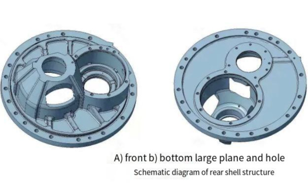
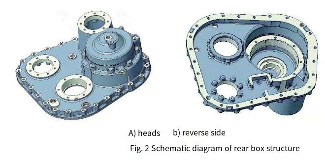
The complex and irregular structure of box-type parts poses machining challenges. For instance, the rear housing (as shown in Figure 1) cannot have its bottom plane and holes machined in a single clamping, and multiple clampings can compromise plane accuracy. Similarly, the rear box (Figure 2) has a large suspended area at the bottom after positioning, which, due to thin walls, may deform during machining, leading to deviations in plane flatness and dowel hole positional accuracy. Additionally, ensuring positional and coaxial accuracy of holes is critical.
Casting blanks typically have a 5 mm machining allowance per side. Depending on subsequent press-fitting operations, a decision is made whether to cast temporary process bosses, which may be removed after machining based on assembly requirements. The machining process follows the principle of separating rough and finish machining, prioritizing planes before holes, and adopting a scientific, centralized approach. The process is divided into rough machining, semi-finish machining, and finish machining to balance allowances. Rough machining leaves a 2 mm allowance for finish machining, while semi-finish machining leaves 0.2–0.5 mm. To minimize internal stresses and enhance machining stability, both the cast blank and rough-machined parts undergo aging treatment.
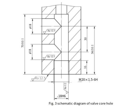
The machining sequence is as follows: rough scribing → rough turning of ends → precise scribing → semi-finish and finish machining of ends → side machining. When drilling, half-wall cutting should be avoided to ensure precision for critical holes. For example, valve core holes (Figure 3) require machining the φ18H7 hole first, followed by the two φ18 mm side holes.
Machining Equipment
Selecting appropriate machining equipment requires a thorough understanding of workshop equipment capabilities and workpiece dimensions. Rough machining typically employs vertical lathes, while semi-finish and finish machining use CNC vertical lathes. End machining is performed on vertical machining centers, and side machining utilizes horizontal machining centers or horizontal milling-boring machines.
For machining centers, periodic spindle runout checks are essential to maintain precision. For horizontal machining centers, the minimum rotational increment of the worktable must be considered, especially for radial holes with centerlines at non-integer angles relative to the workpiece centerline. Equipment with integer-degree increments cannot meet the precision requirements for such holes. To maintain rotational accuracy and extend equipment life, the worktable should rotate in one direction (clockwise or counterclockwise) to complete all peripheral machining tasks in a single cycle.
| Equipment Type | Machining Task | Key Parameters |
|---|---|---|
| Vertical Lathe | Rough Machining | Max workpiece diameter: 2000 mm, spindle speed: 10–500 rpm |
| CNC Vertical Lathe | Semi-Finish/Finish Machining | Positioning accuracy: ±0.01 mm, spindle speed: 20–1000 rpm |
| Vertical Machining Center | End Machining | Table size: 1000×800 mm, spindle runout: ≤0.005 mm |
| Horizontal Machining Center | Side Machining | Min rotational increment: 0.001°, table load: 1000 kg |
Tooling Design
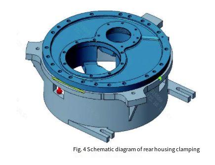
Tooling design significantly impacts machining efficiency, particularly for batch production. Dedicated tooling reduces setup time by allowing one-time alignment, enabling workpieces to be positioned using scribed lines. Tooling bases are made from HT250 material, subjected to aging treatment to eliminate internal stresses, and machined for precision. For the rear housing (Figure 4), the tooling base includes a milled slot for the front face (yellow surface) and a positioning face (green surface, milled with a φ20 mm cutter).
Positioning elements such as pins, shafts, and rings are made from 45 steel, heat-treated for enhanced hardness and wear resistance. Clamping plates and spacers use Q235 or Q355 steel. The tooling base contact area with the worktable is minimized by designing a hollow base, and spacers reduce contact between the tooling and workpiece to ensure flatness. The tooling structure must avoid interference with tools or spindles. When shared between vertical and horizontal machining centers, the base height is adjusted to account for the distance between the spindle and worktable in horizontal setups.
Tool Selection
Tool selection is critical for achieving high machining efficiency and precision. For large planes, face milling cutters are preferred due to their high cutting efficiency. For end-face holes with sealing bevels, composite tools are designed to replace small-diameter milling cutters for interpolation milling. Dowel holes with diameters ≥30 mm are machined with boring tools, while those <30 mm use reamers.
Special attention is given to non-standard tools, such as those for machining slender holes, large-diameter holes, or metric/imperial threaded holes. After reviewing the part design, process engineers compile a tool list, cross-referencing with the tool management center’s inventory to identify shortages. Standard tools are procured, while extended or custom tools (e.g., extended boring tools or large-diameter cutters) are planned in advance due to their 1–2 month production lead time. Extended tools are selected based on toolholder size and required length, but their use is minimized to avoid vibration.
Clamping Methods
Clamping involves positioning and securing the workpiece, with specific methods tailored to box-type parts.
Positioning
Positioning methods include rim positioning, rim with dowel pins, or dual-pin/dual-shaft positioning. Rim positioning uses hole-shaft clearance fits. To ensure rapid positioning, the engagement length between the workpiece and positioning pins or shafts is kept at 8–12 mm. A common configuration uses one cylindrical pin and one diamond-shaped pin, with the diamond pin’s apex pointing toward the cylindrical pin’s center. For dual-shaft positioning with height differences, the positioning surface is milled flat during initial trials to eliminate errors from tooling wear.
Clamping
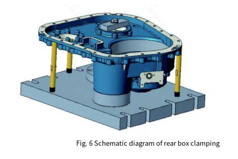
Edges with a width ≥5 mm on the back of the assembly face are suitable for standard clamping plates. If warping occurs after positioning, shims (e.g., copper or paper) are used to eliminate gaps before clamping. When the contact area between the positioning surface and tooling base is large, spacers are employed to reduce contact, with clamping applied at solid points to avoid deformation from suspended clamping. For the rear box (Figure 6), auxiliary supports are added at weak or suspended areas to enhance flatness and dowel hole positional accuracy.
For parts requiring milling and drilling on large planes (Figure 4), multiple clampings are typically needed. To improve flatness, transitional threaded holes are used to allow single-clamping machining. Red bolts at three window locations (Figure 4) secure the workpiece through pre-machined M14-6H threaded holes. After plane and hole machining, the bolts are loosened, the machined surface is clamped with plates, and the M14-6H holes are enlarged to the final φ16 mm specification.
Conclusion
The machining of box-type parts requires careful consideration of workpiece features, equipment capabilities, tooling design, tool selection, and clamping methods. Key practices include ensuring sufficient machining allowances and separating rough and finish machining to accommodate casting defects, avoiding polar coordinate programming for critical holes to allow coordinate adjustments, and selecting appropriate tools and equipment based on part complexity. By designing optimized positioning and clamping tooling and addressing specific machining requirements, high-quality parts can be produced efficiently, meeting precision and performance standards.