Prototyping propellers involves a multidisciplinary approach, combining aerodynamics, materials science, and precision manufacturing. This guide provides a detailed roadmap for designing, fabricating, and testing propellers, with a focus on practical considerations and technical parameters. Whether for unmanned aerial vehicles (UAVs), marine applications, or small aircraft, the process requires careful planning to achieve efficiency, durability, and performance. The following sections outline each phase, from conceptual design to final testing, with actionable insights and specifications.
Understanding Propeller Fundamentals
Before embarking on prototyping, a solid grasp of propeller mechanics is essential. Propellers convert rotational energy into thrust, governed by principles of aerodynamics and fluid dynamics. Key parameters include blade pitch, diameter, number of blades, and material properties, all of which influence performance.
Key Aerodynamic Principles
Propellers operate by accelerating fluid (air or water) to generate thrust. The angle of attack, determined by blade pitch, affects lift and drag forces. For air propellers, Bernoulli's principle and Newton's third law explain thrust generation. In marine environments, hydrodynamic forces dominate, requiring adjustments for water's higher density (approximately 1000 kg/m³ compared to air's 1.225 kg/m³ at sea level). Typical parameters include:
- Blade Pitch: Angle of blade relative to the plane of rotation, typically 10–30 degrees for UAVs.
- Diameter: Ranges from 0.2 m for small drones to 2 m for light aircraft.
- Chord Length: Blade width, often 5–10% of diameter at the mid-span.
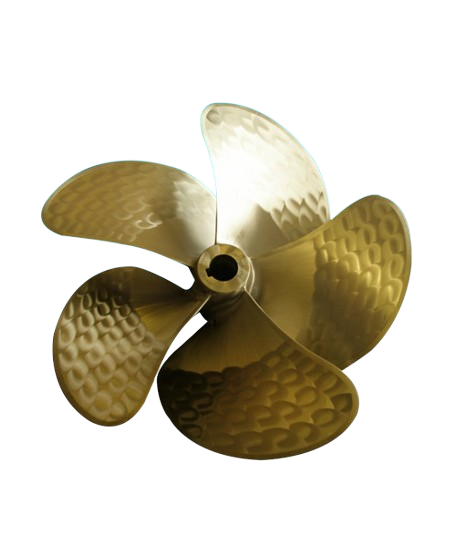
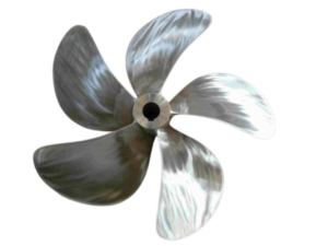
Types of Propellers
Propellers vary by application. Fixed-pitch propeller are common in UAVs due to simplicity, while variable-pitch propeller allow in-flight adjustments for efficiency. Marine propellers, such as screw propellers, prioritize torque over speed. Folding propellers, used in drones, reduce drag during gliding. Each type demands specific design considerations, detailed in later sections.
Designing the Propeller
The design phase translates performance requirements into a physical model. Computational tools and empirical data guide the process, balancing efficiency, weight, and structural integrity. This section covers software, parameters, and design iterations.
Selecting Design Software
Modern propeller design relies on computational fluid dynamics (CFD) and computer-aided design (CAD) software. Tools like ANSYS Fluent, SolidWorks, and XFOIL enable precise modeling. For example, XFOIL calculates airfoil performance for 2D blade sections, while Fluent simulates 3D flow. Open-source alternatives, such as OpenFOAM, suit budget-conscious projects. Key design inputs include:
- Reynolds Number: Typically 10⁵–10⁶ for small propellers, affecting lift and drag.
- Advance Ratio (J): Ratio of forward speed to rotational speed, often 0.5–1.5 for UAVs.
- Thrust Coefficient (C_T): Dimensionless thrust metric, targeting 0.1–0.3 for efficiency.
Defining Blade Geometry
Blade geometry determines performance. Designers select airfoil shapes (e.g., NACA 4412 for low-speed applications) and define parameters like twist angle (5–15 degrees from root to tip) and taper ratio (0.5–0.8 for structural efficiency). A typical UAV propeller might have:
- Diameter: 0.3 m
- Number of Blades: 2–4
- Pitch-to-Diameter Ratio: 0.4–0.8
- Tip Speed: Below 0.9 Mach (300 m/s in air) to minimize noise.
Iterative simulations refine these parameters, optimizing for thrust-to-power ratio.
Material Selection
Material choice impacts weight, strength, and cost. Common materials include composites, metals, and plastics, each suited to specific applications. This section explores options and their properties.
Composite Materials
Carbon fiber and glass fiber composites dominate UAV and high-performance propellers due to their high strength-to-weight ratio. Carbon fiber offers a tensile strength of 3.5–7 GPa and density of 1.8 g/cm³, compared to aluminum's 2.7 g/cm³. Layup techniques, such as 0°/90° fiber orientation, enhance stiffness. Typical specifications:
- Young's Modulus: 230 GPa for carbon fiber.
- Fatigue Limit: 10⁷ cycles for composites vs. 10⁵ for metals.
Metals and Plastics
Aluminum alloys (e.g., 6061-T6) suit marine propellers, with a yield strength of 275 MPa and corrosion resistance via anodizing. Plastics like nylon or ABS are cost-effective for small drones but have lower durability (tensile strength: 40–80 MPa). Material selection considers:
- Operating Environment: Saltwater exposure favors stainless steel or coated composites.
- Cost: Plastics cost $1–5/kg, while carbon fiber ranges from $20–50/kg.
Manufacturing the Prototype
Fabrication transforms designs into physical prototypes. Techniques range from additive manufacturing to traditional machining, each with trade-offs in precision and cost.
Additive Manufacturing
3D printing, using materials like PLA or resin, enables rapid prototyping for small propellers. Fused deposition modeling (FDM) achieves tolerances of ±0.1 mm, suitable for initial tests. For high-strength parts, selective laser sintering (SLS) with nylon-carbon blends offers better durability. Parameters include:
- Layer Thickness: 0.05–0.2 mm for smooth surfaces.
- Print Speed: 50–100 mm/s to balance quality and time.
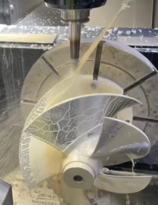
Traditional Manufacturing
CNC machining and molding suit high-precision or large-scale propellers. CNC mills achieve tolerances of ±0.01 mm, ideal for aluminum or composite blades. Injection molding scales production but requires molds costing $5,000–$20,000. Surface finish (Ra 0.8–1.6 µm) ensures aerodynamic efficiency.
Testing and Validation
Testing verifies performance against design goals. Static and dynamic tests measure thrust, efficiency, and durability, while field tests assess real-world behavior.
Static Testing
Static tests measure thrust and torque at fixed RPMs. A test rig with a load cell and tachometer records data. For a 0.3 m UAV propeller at 10,000 RPM, expected thrust is 5–15 N, with a power consumption of 100–300 W. Key metrics include:
- Efficiency (η): Thrust-to-power ratio, targeting 0.7–0.85.
- Torque Coefficient (C_Q): Typically 0.01–0.03.
Dynamic and Field Testing
Dynamic tests simulate operating conditions, such as varying RPMs or angles of attack. Wind tunnels provide controlled environments, with airspeeds of 10–50 m/s for UAVs. Field tests on actual vehicles reveal practical issues, like vibration or noise (target: <80 dB at 1 m). Data informs design iterations.
Optimization and Iteration
Prototyping is iterative. Test results guide refinements, such as adjusting blade twist or material thickness. Machine learning algorithms can optimize designs by analyzing CFD data, reducing iterations. Typical adjustments include:
- Increasing Pitch: Boosts thrust but raises power demand.
- Reducing Weight: Thinner blades (1–2 mm at tip) lower inertia.
Frequently Asked Questions
What software is best for propeller design?
ANSYS Fluent and SolidWorks are industry standards for CFD and CAD, respectively. OpenFOAM is a cost-effective alternative for CFD simulations.
Which material is ideal for UAV propellers?
Carbon fiber composites offer the best strength-to-weight ratio, though nylon is suitable for low-cost prototypes.
How long does propeller prototyping take?
Design and initial prototyping take 2–4 weeks, with testing and iteration adding 1–3 months, depending on complexity.
What are common testing failures?
Blade deformation, excessive vibration, or insufficient thrust often result from poor material choice or inaccurate CFD models.