Prototyping a robotic arm involves integrating mechanical design, electronics, and control systems to create a functional manipulator for tasks ranging from industrial automation to research and hobbyist projects. This guide outlines the process, from conceptual design to testing, with detailed technical parameters and practical considerations. The focus is on creating a prototype that balances performance, cost, and scalability, suitable for applications like pick-and-place operations, surgical assistance, or educational platforms. Each phase—design, material selection, actuation, control, manufacturing, and testing—is explored in depth to provide a clear roadmap.
Understanding Robotic Arm Fundamentals
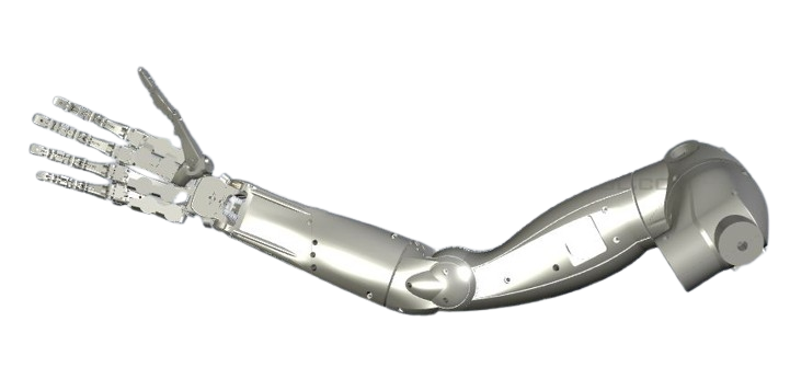
A robotic arm is a programmable manipulator with multiple degrees of freedom (DOF), typically 4–7, mimicking human arm motion. It consists of links (rigid segments), joints (rotary or prismatic), actuators (motors or hydraulics), and an end effector (gripper, tool, or sensor). The design must account for workspace, payload, precision, and speed, tailored to the intended application.
Key Kinematic Principles
Kinematics governs the motion of robotic arms. Forward kinematics calculates the end effector’s position based on joint angles, while inverse kinematics determines joint angles for a desired position. For a 6-DOF arm, the Denavit-Hartenberg (DH) parameters define the kinematic chain. Typical specifications include:
- Degrees of Freedom: 4–6 for most prototypes, enabling 3D positioning and orientation.
- Workspace Radius: 0.5–1.5 m for small to medium arms.
- Joint Range: ±180° for rotary joints, 0.1–0.5 m for prismatic joints.
Types of Robotic Arms
Robotic arms vary by structure and application. Articulated arms, with rotary joints, suit flexible tasks like welding. SCARA (Selective Compliance Assembly Robot Arm) designs excel in planar tasks like assembly. Cartesian arms, using linear axes, offer high precision for 3D printing. Each type influences prototyping choices, from joint design to actuator selection.
Designing the Robotic Arm
The design phase translates functional requirements into a mechanical and electronic blueprint. Computer-aided design (CAD) tools, kinematic simulations, and payload analysis ensure the arm meets performance goals. This section covers tools, parameters, and design iterations.
Selecting Design Software
CAD software like SolidWorks, Fusion 360, or FreeCAD enables 3D modeling of links and joints. Simulation tools, such as MATLAB with Robotics Toolbox or ROS (Robot Operating System) with Gazebo, analyze kinematics and dynamics. Open-source options like Blender suit visualization for hobbyists. Design inputs include:
- Payload Capacity: 0.5–5 kg for small prototypes, 10–50 kg for industrial arms.
- Reach: 0.7–1.2 m for typical prototypes.
- Repeatability: ±0.1 mm for precision tasks, ±1 mm for general use.
Defining Arm Geometry
Geometry defines the arm’s structure. Links are typically 0.1–0.5 m long, with cross-sections (e.g., hollow tubes or I-beams) optimized for strength-to-weight ratio. Joints use bearings or bushings, with angular resolution of 0.01–0.1°. A sample 5-DOF arm might have:
- Base Joint: 360° rotation, torque 10–50 Nm.
- Elbow Joint: ±135°, torque 5–20 Nm.
- End Effector: Gripper with 0–50 mm opening, 1–5 kg gripping force.
Finite element analysis (FEA) in tools like ANSYS validates structural integrity under load.
End Effector Design
The end effector depends on the task. Grippers, with parallel or angular jaws, handle objects of 0.01–0.5 kg. Vacuum cups suit flat surfaces, while tools like welders or drills require custom mounts. Specifications include:
- Gripper Force: 10–100 N.
- Actuation Time: 0.1–0.5 s for opening/closing.
- Weight: 0.1–1 kg to minimize arm load.
Material Selection
Materials balance strength, weight, and cost. Aluminum, composites, and plastics dominate, with choices driven by load, environment, and manufacturing constraints.
Metals
Aluminum alloys (e.g., 6061-T6) offer a yield strength of 275 MPa and density of 2.7 g/cm³, ideal for links and joints. Stainless steel (e.g., 304) suits corrosive environments, with a tensile strength of 500–700 MPa. Typical parameters:
- Young’s Modulus: 70 GPa for aluminum, 190 GPa for steel.
- Fatigue Limit: 10⁷ cycles for aluminum, 10⁸ for steel.
Composites and Plastics
Carbon fiber composites, with tensile strength of 3.5–7 GPa and density of 1.8 g/cm³, reduce weight for high-performance arms. ABS or PLA plastics, with tensile strength of 40–80 MPa, suit low-cost prototypes. Considerations include:
- Cost: Aluminum at $2–5/kg, carbon fiber at $20–50/kg.
- Thermal Expansion: 23 µm/m·K for aluminum, 0.8 µm/m·K for carbon fiber.
Actuator Selection
Actuators provide motion, with choices between electric motors, pneumatics, or hydraulics. Electric motors dominate due to precision and ease of control.
Electric Motors
DC servo or stepper motors are common, offering torque of 0.5–10 Nm and speeds of 100–3000 RPM. Brushless DC motors (BLDC) provide higher efficiency (80–90%) and lifespan (10,000+ hours). Parameters include:
- Torque-to-Weight Ratio: 1–5 Nm/kg for servos.
- Encoder Resolution: 1000–4000 counts per revolution.
Pneumatic and Hydraulic Actuators
Pneumatics suit high-speed, low-precision tasks, with pressures of 5–10 bar. Hydraulics, at 50–200 bar, handle heavy payloads (50–500 kg) but require complex systems. Both are less common in prototypes due to cost and maintenance.
Control Systems
Control systems coordinate motion, using microcontrollers, sensors, and software. Real-time feedback ensures accuracy and safety.
Hardware Components
Microcontrollers like Arduino, Raspberry Pi, or STM32 handle computation. Sensors, such as encoders (for position) and IMUs (for orientation), provide feedback. Typical setup:
- Processing Speed: 16–400 MHz for microcontrollers.
- Sensor Resolution: 0.01° for encoders, 0.1 g for accelerometers.
Software and Algorithms
Control algorithms, like PID (Proportional-Integral-Derivative), maintain precision. ROS enables modular programming, while Python or C++ suits custom applications. Sampling rates of 100–1000 Hz ensure smooth operation.
Manufacturing the Prototype
Manufacturing transforms designs into physical components. Additive and subtractive methods cater to different needs, from rapid prototyping to precision parts.
Additive Manufacturing
3D printing with PLA, ABS, or resin creates complex geometries with tolerances of ±0.1 mm. Fused deposition modeling (FDM) suits initial prototypes, while stereolithography (SLA) offers smoother finishes (Ra 0.4 µm). Parameters include:
- Layer Thickness: 0.05–0.3 mm.
- Print Speed: 40–100 mm/s.
Subtractive Manufacturing
CNC machining, using mills or lathes, achieves tolerances of ±0.01 mm for aluminum or steel parts. Laser cutting suits flat components, with kerf widths of 0.1–0.5 mm. Surface finish (Ra 0.8–1.6 µm) ensures smooth joint operation.
Testing and Validation
Testing verifies performance against design goals. Static, dynamic, and task-specific tests assess accuracy, strength, and reliability.
Static Testing
Static tests measure joint torque and structural integrity. A load cell records forces, with expected torque of 5–50 Nm per joint. Deflection under load (e.g., 0.1–1 mm at 5 kg) indicates material suitability.
Dynamic and Task-Specific Testing
Dynamic tests evaluate motion at 0.1–1 m/s, checking repeatability (±0.1–1 mm). Task-specific tests, like pick-and-place cycles (100–1000 repetitions), assess endurance. Vibration analysis (target: <0.1 g at 50 Hz) ensures stability.
Optimization and Iteration
Prototyping is iterative. Test data guides refinements, such as reducing link weight (e.g., 0.5–1 kg per link) or increasing motor torque (10–20%). Machine learning can optimize control algorithms, minimizing error by 5–10%.
Frequently Asked Questions
What is the best software for robotic arm design?
SolidWorks and Fusion 360 are ideal for CAD, while ROS and MATLAB suit simulation and control. FreeCAD is a budget-friendly alternative.
Which actuators are best for small robotic arms?
DC servo or BLDC motors offer precision and efficiency for payloads under 5 kg. Stepper motors suit low-cost prototypes.
How long does prototyping a robotic arm take?
Design and initial fabrication take 4–8 weeks, with testing and iteration adding 2–6 months, depending on complexity.
What are common prototyping challenges?
Joint backlash, insufficient torque, or control instability often arise from poor design or component mismatch.
How is repeatability tested?
Repeatability is tested by commanding the arm to a fixed position multiple times, measuring deviation (target: ±0.1–1 mm).