Splines are mechanical components used to connect rotating elements and transmit torque in machinery. They consist of ridges or teeth on a shaft that mesh with grooves in a mating component, ensuring efficient power transfer and alignment. This article provides a technical overview of splines, covering their types, design parameters, applications, and limitations, structured for clarity and precision in mechanical engineering contexts.
Definition and Function of Splines
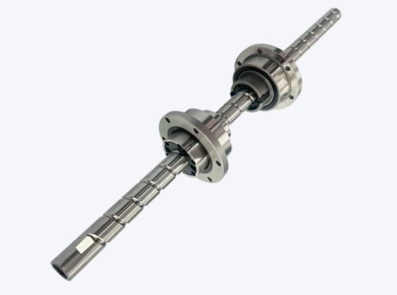
In mechanical engineering, splines are features on a shaft or hub, typically in the form of teeth or ridges, designed to engage with corresponding grooves in a mating part. Their primary function is to transmit torque between components while maintaining precise alignment and allowing relative axial motion in some cases. Splines are critical in applications requiring high torque, such as automotive transmissions, industrial machinery, and aerospace systems.
Unlike keyways, which use a single key to transmit torque, splines distribute load across multiple teeth, reducing stress concentration and improving durability. They are designed to handle both rotational and axial forces, depending on the configuration.
Types of Splines
Splines are classified based on their geometry, tooth profile, and application. The following table summarizes common spline types and their characteristics.
| Spline Type | Tooth Profile | Characteristics | Applications |
|---|---|---|---|
| Involute Spline | Involute | Curved teeth, high strength, self-centering | Automotive transmissions, aerospace |
| Parallel Spline | Straight-sided | Simple design, lower cost, less precise | General machinery, couplings |
| Serrated Spline | Sawtooth-shaped | High torque, limited axial movement | Heavy machinery, pumps |
| Crowned Spline | Curved tooth surface | Accommodates misalignment, reduced wear | Flexible couplings, marine propulsion |
Involute splines, defined by standards like ANSI B92.1 or DIN 5480, are the most common due to their strength and self-centering properties. Parallel splines are simpler but less precise, while serrated and crowned splines cater to specialized needs.
Design Parameters of Splines
Spline design involves several key parameters to ensure performance and compatibility. These include:
- Number of Teeth (\( N \)): Typically ranges from 6 to 50, balancing torque capacity and manufacturing complexity. More teeth increase load distribution but reduce tooth thickness.
- Module (\( m \)): For metric splines, the module is defined as \( m = \frac{d}{N} \), where \( d \) is the pitch diameter (mm). Common values range from 0.5 to 10 mm.
- Pressure Angle (\( \alpha \)): Usually 30° or 37.5° for involute splines, affecting load distribution and strength. A 30° angle is standard per ANSI B92.1.
- Major and Minor Diameters: The major diameter (outer diameter of external spline) and minor diameter (root diameter) define the spline’s size. For example, a 25 mm major diameter spline with 16 teeth has a minor diameter of approximately 21 mm.
- Fit Type: Spline fits (e.g., major diameter fit, side fit) determine clearance and alignment. Side-fit splines (per ANSI B92.1) allow tighter tolerances, with backlash typically 0.025–0.1 mm.
- Length of Engagement: The axial length of spline contact, typically 1–2 times the pitch diameter, affects torque capacity.
These parameters are calculated using standards like ISO 4156 or SAE J498, ensuring compatibility and performance.
Manufacturing of Splines
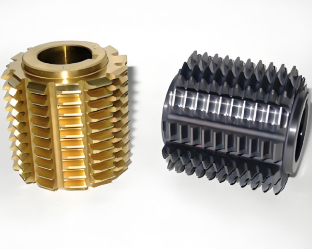
Splines are manufactured using processes like hobbing, milling, or broaching for external splines, and shaping or broaching for internal splines. Key considerations include:
Material Selection
Common materials include alloy steels (e.g., AISI 4140, 4340) for high strength, with hardness typically 40–50 HRC after heat treatment. Stainless steel or titanium may be used for corrosion resistance in aerospace applications.
Machining Precision
Tolerances for spline teeth are tight, often ±0.01 mm for critical dimensions like tooth thickness. Standards like DIN 5480 specify tolerances for major diameter, tooth profile, and backlash.
Surface Treatment
Surface treatments like nitriding or coating (e.g., DLC) enhance wear resistance. For example, nitriding increases surface hardness to 60–65 HRC, extending spline life under high torque.
Applications of Splines
Splines are used across industries for reliable torque transmission. Key applications include:
Automotive Transmissions
Involute splines connect transmission shafts to gears, handling torques up to 5000 Nm in heavy-duty vehicles. For example, a 6-speed gearbox may use a 25 mm spline with 23 teeth and a 30° pressure angle.
Aerospace Systems
Splines in jet engines connect turbine shafts to compressors, requiring high precision and lightweight materials like titanium. Crowned splines accommodate slight misalignments during operation.
Industrial Machinery
Splines in pumps, motors, and couplings transmit torque in harsh environments. Serrated splines are used in high-torque applications like hydraulic pumps, with torque capacities exceeding 10,000 Nm.
Robotics and Automation
Small-scale splines connect servo motors to robotic joints, requiring precise fits (e.g., 0.02 mm backlash) for accurate motion control.
Implementation Considerations
Designing and implementing splines involves addressing several technical factors:
Alignment and Fit
Proper alignment is critical to prevent uneven load distribution. Side-fit splines ensure precise centering, with tolerances specified by standards like ISO 4156 (e.g., H7/h6 fit).
Lubrication
Lubrication reduces wear and friction. Grease (e.g., NLGI Grade 2) or oil (ISO VG 68) is used, with viscosity chosen based on operating temperature (e.g., 40–100°C).
Torque and Load Analysis
Finite element analysis (FEA) is used to evaluate stress distribution. For a spline with 20 teeth and 50 mm diameter, FEA may show peak stresses of 150 MPa under 2000 Nm torque.
| Parameter | Typical Value | Impact |
|---|---|---|
| Backlash | 0.025–0.1 mm | Affects alignment and noise |
| Shear Stress | 150–250 MPa | Determines torque capacity |
| Surface Hardness | 40–60 HRC | Influences wear resistance |
Limitations and Challenges
Splines, while robust, face several limitations that engineers must address:
- Wear and Fatigue: High torque and cyclic loading can cause tooth wear or fatigue failure, especially in poorly lubricated systems. For example, a spline operating at 3000 rpm may experience fretting wear after 10^6 cycles.
- Manufacturing Complexity: Tight tolerances (e.g., ±0.01 mm) increase production costs and require advanced machining like CNC hobbing.
- Misalignment Sensitivity: Non-crowned splines are sensitive to misalignment, leading to uneven load distribution and potential failure. Misalignment of 0.5° can increase stress by 20%.
- Space Constraints: Splines require sufficient axial length for engagement, limiting their use in compact designs.
These limitations necessitate careful design, material selection, and maintenance to ensure reliability.
Conclusion
Splines are essential mechanical components for torque transmission, offering high strength and precision in applications from automotive to aerospace. By understanding their types, design parameters, and manufacturing processes, engineers can optimize spline performance. While limitations like wear and manufacturing complexity exist, proper design and maintenance mitigate these issues, making splines a cornerstone of mechanical engineering.
Splines: Design and Applications FAQ
What is a spline?
A spline is a mechanical component with ridges or teeth (external or internal) that mesh with corresponding grooves or teeth on a mating part. It is used to transmit torque while allowing for relative motion (e.g., sliding or rotation) between connected shafts or components. Common applications include automotive transmissions, machinery, and aerospace systems.
What factors affect spline pricing?
Complexity: Helical or involute profiles cost more than straight rectangular splines.
Materials: Alloy steels or titanium for high - stress applications increase costs.
Precision: Tighter tolerances (e.g., for aerospace) require advanced machining.
Quantity: Mass production via cold forming reduces unit costs; small batches favor broaching or milling.
Surface treatment: Processes like nitriding or plating add to the cost.