High-speed cutting of aluminum alloy impellers is a critical process in industries such as aerospace, automotive, and energy, where precision, efficiency, and tool longevity are paramount. This guide provides a detailed, technical analysis of tool selection and durability considerations for machining aluminum alloy impellers. It focuses on material properties, cutting parameters, tool materials, geometries, and coatings, ensuring a systematic approach to achieving optimal machining outcomes.
Material Properties of Aluminum Alloys for Impellers
Aluminum alloys are widely used for impellers due to their high strength-to-weight ratio, corrosion resistance, and machinability. Common alloys include Al6061, Al7075, and Al2024, each with distinct mechanical and thermal properties that influence tool selection and durability.
Al6061, a precipitation-hardened alloy with magnesium and silicon, offers good machinability and moderate strength, making it suitable for general-purpose impellers. Al7075, with zinc as the primary alloying element, provides high strength but poses challenges due to increased tool wear. Al2024, with copper as the main alloying component, is common in aerospace impellers for its high strength-to-weight ratio but has lower corrosion resistance, requiring specific machining considerations.
| Alloy | Main Alloying Elements | Tensile Strength (MPa) | Hardness (HB) | Thermal Conductivity (W/m·K) | Applications |
|---|---|---|---|---|---|
| Al6061 | Mg, Si | 310 | 95 | 167 | General-purpose impellers |
| Al7075 | Zn | 570 | 150 | 130 | High-strength aerospace impellers |
| Al2024 | Cu | 470 | 120 | 121 | Aerospace structural components |
The low melting point (approximately 580–660°C) and high ductility of aluminum alloys can lead to material adhesion on tools, causing built-up edge (BUE) formation. This necessitates careful selection of cutting tools and parameters to minimize friction and heat generation.
Tool Material Selection for High-Speed Cutting
Selecting the appropriate tool material is critical for high-speed cutting of aluminum alloy impellers. The primary tool materials used are cemented carbide, polycrystalline diamond (PCD), and coated carbide tools, each offering specific advantages.
Cemented Carbide (K10, K20): Carbide tools, particularly K10 and K20 grades, are widely used due to their balance of hardness and toughness. For aluminum alloys with low silicon content (<12%), K10 carbide tools are effective, providing cutting speeds of 2000–4000 m/min and feed rates of 3–12 m/min. These tools are cost-effective and suitable for general machining.
Polycrystalline Diamond (PCD): PCD tools are ideal for high-silicon aluminum alloys (Si >12%) due to their exceptional hardness and wear resistance. They support cutting speeds up to 1100 m/min and feed rates of 0.125 mm/r for alloys with 16–18% silicon content. PCD tools are particularly effective in dry cutting, reducing environmental impact.
Coated Carbide Tools: Coatings such as TiN, TiAlN, and TiN/TiAlN enhance tool performance by reducing friction and improving thermal stability. TiN/TiAlN coatings are particularly effective for dry machining, offering high wear resistance at cutting speeds of 1500–5000 m/min. However, TiN coatings may result in higher surface roughness compared to TiAlN.
The choice of tool material depends on the alloy composition, machining conditions, and whether coolant is used. For high-speed machining, PCD and coated carbide tools are preferred for their ability to maintain sharpness and resist adhesion.
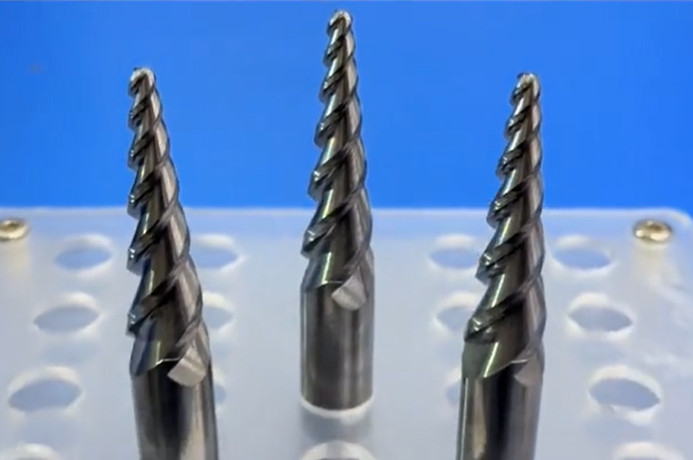
Tool Geometry and Its Impact on Durability
Tool geometry significantly affects cutting performance and durability. Key parameters include rake angle, relief angle, helix angle, and chamfer width, each influencing chip formation, cutting forces, and tool life.
Rake Angle: A positive rake angle of 12°–18° is recommended for aluminum alloys to reduce cutting forces and improve chip evacuation. Higher rake angles decrease the load on the tool but may reduce edge strength, necessitating a balance based on alloy hardness.
Relief Angle: A relief angle of 10°–18° prevents rubbing between the tool and workpiece, reducing heat generation and tool wear. For softer alloys like Al6061, a larger relief angle is preferred to minimize adhesion.
Helix Angle: A helix angle of 35°–45° is optimal for high-speed milling of aluminum alloys. A 45° helix angle is particularly effective for finishing operations, as it enhances chip evacuation and reduces cutting forces. For roughing, a 35°–40° helix angle balances chip removal and tool stability.
Chamfer Width: A chamfer width of 0.17 mm with a chamfer angle of 7.3° or 18.3° optimizes cutting force and temperature control during finishing of thin-walled aluminum alloy components, such as impellers.
Proper geometry reduces vibration, improves surface finish, and extends tool life. For impellers with complex geometries, tools with chipbreaker designs or variable helix angles (approximately 34°) can further enhance performance by minimizing chatter.
Cutting Parameters for High-Speed Machining
Optimizing cutting parameters—cutting speed, feed rate, and depth of cut—is essential for achieving high productivity and tool durability. These parameters must be tailored to the specific aluminum alloy and machining operation.
Cutting Speed: For wrought aluminum alloys (e.g., Al6061, Al7075), cutting speeds of 800–1500 m/min are recommended. For cast alloys with higher silicon content, speeds range from 100–500 m/min, depending on tool material. For example, Al7075 supports speeds of 3000–8000 rpm, while Al2024 operates effectively at 2000–7000 rpm.
Feed Rate: Feed rates typically range from 0.02–0.10 mm/tooth, depending on the cutting edge diameter. For a 2–4 mm diameter tool, a feed rate of 0.02–0.03 mm/tooth is suitable, while larger tools (9–12 mm) can handle 0.10 mm/tooth. Higher feed rates improve chip thinning and prevent buildup but must be balanced to avoid excessive tool wear.
Depth of Cut: Shallow depths of cut (0.1–0.5 mm) are preferred for aluminum alloys to minimize tool deflection and heat generation. For thin-walled impeller blades, a smaller axial depth of cut and larger radial depth are beneficial to reduce cutting forces and residual stress.
| Alloy | Cutting Speed (m/min) | Feed Rate (mm/tooth) | Depth of Cut (mm) |
|---|---|---|---|
| Al6061 | 800–1500 | 0.02–0.05 | 0.1–0.5 |
| Al7075 | 3000–8000 (rpm) | 0.06–0.12 | 0.1–0.3 |
| Al2024 | 2000–7000 (rpm) | 0.02–0.10 | 0.1–0.4 |
These parameters should be adjusted based on real-time monitoring of tool wear, surface finish, and chip formation to maintain consistent performance.
Coolant and Lubrication Strategies
Aluminum alloys’ high thermal conductivity and low melting point make coolant and lubrication strategies critical for tool durability and surface quality. Common approaches include dry machining, minimum quantity lubrication (MQL), and conventional cooling.
Dry Machining: High-speed cutting, particularly with PCD tools, can be performed without coolant to reduce environmental impact. Extraordinarily high-speed cutting (EHS) leverages heat softening to reduce friction coefficients (down to 0.170), minimizing adhesion issues.
Minimum Quantity Lubrication (MQL): MQL applies a thin film of lubricant to reduce friction and provide minimal cooling, suitable for precise operations. It improves chip evacuation and reduces BUE formation compared to dry cutting.
Conventional Cooling: Flood cooling is effective for controlling cutting temperatures (200–400°C) and reducing tool wear, particularly for softer alloys like Al6061. However, it may lead to mildew formation if corrosion-inhibiting properties are inadequate.
The choice of coolant depends on the machining environment and alloy properties. For high-silicon alloys, dry machining with PCD tools is often preferred, while MQL is suitable for precision finishing of wrought alloys.
Tool Wear Mechanisms and Durability Analysis
Tool wear in aluminum alloy machining is primarily driven by adhesion, abrasion, and thermal effects. Understanding these mechanisms is essential for extending tool life.
Adhesion Wear: The low melting point and high ductility of aluminum alloys cause material to adhere to the tool, forming a built-up edge (BUE). This increases cutting forces and degrades surface quality. Coated tools (e.g., TiAlN) and high cutting speeds reduce adhesion by minimizing contact time.
Abrasion Wear: High-silicon alloys increase abrasive wear due to hard inclusions. PCD tools are highly resistant to abrasion, making them ideal for such alloys. Carbide tools experience higher wear rates in these conditions.
Thermal Wear: Cutting temperatures of 200–400°C can soften tool materials, accelerating wear. Coatings like TiN/TiAlN provide thermal stability, while optimized cutting speeds and coolant use help manage heat generation.
Tool life can be extended by 30–40% compared to steel machining due to aluminum’s lower hardness. Vibration control techniques, such as tuned mass dampers (TMD), can further reduce wear by minimizing cutting forces and thermal effects.
Surface Integrity and Chip Morphology
Surface integrity and chip morphology are critical indicators of machining quality. High-speed cutting of aluminum alloys can achieve surface roughness (Ra) of 0.8–1.6 µm with optimized parameters. Key factors influencing surface integrity include:
Cutting Parameters: Higher cutting speeds and moderate feed rates improve surface finish by reducing burr formation and BUE. For example, a helix angle of 45° minimizes burrs in face milling of Al6061.
Tool Design: Tools with chipbreaker geometry or high helix angles produce short, manageable chips, reducing the risk of chip recutting and improving surface quality.
Coolant Use: MQL and pulsating lubrication strategies enhance chip evacuation, reducing surface defects by up to 25%. Dry machining with PCD tools also produces favorable chip morphology for high-silicon alloys.
Monitoring chip formation and surface roughness during machining ensures consistent quality and helps identify optimal parameter adjustments.
Practical Recommendations for Machining Aluminum Alloy Impellers
To achieve optimal results in high-speed cutting of aluminum alloy impellers, consider the following recommendations:
- Select tool materials based on alloy composition: PCD for high-silicon alloys, coated carbide for wrought alloys.
- Optimize tool geometry with positive rake angles (12°–18°), relief angles (10°–18°), and helix angles (35°–45°).
- Use high cutting speeds (800–1500 m/min for wrought alloys, 100–500 m/min for cast alloys) and moderate feed rates (0.02–0.10 mm/tooth).
- Employ MQL or dry machining for environmental benefits and effective chip evacuation.
- Monitor tool wear and surface quality in real-time to adjust parameters dynamically.
- Use vibration control techniques, such as TMD, to reduce cutting forces and enhance tool life.
By integrating these strategies, manufacturers can achieve high precision, extended tool life, and superior surface quality in machining aluminum alloy impellers.