Precision machining of centrifugal impellers is a complex process requiring high accuracy to meet stringent performance and quality standards, particularly in industries such as aerospace, energy, and industrial fluid management. Centrifugal impellers, critical components in pumps and compressors, demand meticulous control to ensure dimensional accuracy, surface quality, and aerodynamic performance. This guide outlines three key control points: toolpath planning, cutting parameter optimization, and quality inspection. Each point is essential to achieving efficient and precise machining outcomes, ensuring the impeller meets design specifications and operational requirements.
Toolpath Planning
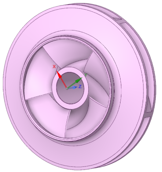
Toolpath planning is the foundation of precision machining for centrifugal impellers. Due to the complex geometry of impellers, which often feature twisted blades, narrow flow channels, and free-form surfaces, effective toolpath planning ensures collision-free machining, minimizes material waste, and maintains surface integrity. The process involves defining the trajectory of the cutting tool, typically using 5-axis CNC machines, to achieve the desired geometry while avoiding interference with the workpiece.
The primary objective of toolpath planning is to generate cutter location (CL) data based on the impeller’s CAD model, which includes the blade and hub surfaces. The blade surfaces, composed of suction and pressure surfaces, are often designed as ruled surfaces, requiring precise tool orientation to prevent overcutting or gouging. The hub, typically an irregular surface, is machined within deep and narrow grooves, adding complexity to the toolpath design.
A key aspect of toolpath planning is the use of flank milling for rough and semi-finish machining. Flank milling, where the side of the cutter removes material, reduces machining time by minimizing path-line length. For example, a study demonstrated that flank milling on a 5-axis machine reduced machining time by optimizing the toolpath for a centrifugal impeller with a 200 mm outer diameter. The toolpath is generated using CAM software such as UG or CATIA, which converts the geometric model into numerical control (NC) code. The tool axis vector is determined using linear interpolation to minimize false contacts between the tool and blade, ensuring high-quality machining.
Another critical consideration is the selection of tool entry and exit points. These points must be carefully mapped to avoid collisions, particularly in areas with high blade torsion or narrow channels. For instance, a 5-axis CNC machine can achieve a tool entry accuracy of ±0.01 mm by using real-time interpolation at the tool drop point. The toolpath must also account for the impeller’s dynamic balance, ensuring symmetry to reduce vibration during operation. This is achieved by setting parameters for blade and runner symmetry in the CAM programming phase.
Simulation plays a vital role in validating toolpaths before machining. Software like VERICUT is used to simulate the NC program, checking for interference, collisions, overcuts, or undercuts. For example, a simulation of a centrifugal impeller with a 5-inch diameter and 0.7-inch blade height confirmed that a toolpath with a [Normal to Part] configuration achieved a surface roughness of Ra 0.8 μm without collisions.
Cutting Parameter Optimization
Optimizing cutting parameters is critical to achieving precision, efficiency, and tool longevity in centrifugal impeller machining. Key parameters include cutting speed, feed rate, depth of cut, and tool selection. These parameters directly influence surface quality, dimensional accuracy, and machining time, particularly when dealing with materials like stainless steel, titanium, or aluminum, commonly used for impellers.
Cutting speed, measured in meters per minute (m/min), determines the rate at which the tool removes material. For stainless steel impellers, a cutting speed of 80-120 m/min is typically recommended to balance material removal rate and tool wear. Titanium, due to its high strength and low thermal conductivity, requires lower speeds, around 40-60 m/min, to prevent excessive heat buildup. Aluminum, being softer, can be machined at higher speeds, up to 200 m/min, to improve efficiency.
Feed rate, expressed in millimeters per tooth (mm/tooth), affects surface finish and tool life. A feed rate of 0.05-0.1 mm/tooth is suitable for finishing operations on impeller blades to achieve a surface roughness of Ra 0.8 μm or better. For roughing, a higher feed rate of 0.15-0.2 mm/tooth can be used to maximize material removal, provided the machine’s stability and tool strength are adequate.
Depth of cut is another critical parameter, particularly for thin-walled impeller blades, which are prone to deformation under excessive cutting forces. A depth of cut ranging from 0.0-1.0 mm is typically used for finishing operations to ensure precision. For example, a centrifugal impeller with a blade thickness of 1 mm was machined with a 0.2 mm depth of cut during finishing to prevent deformation and achieve a dimensional tolerance of ±0.00025 inches.
| Material | Cutting Speed (m/min) | Feed Rate (mm/tooth) | Depth of Cut (mm) |
|---|---|---|---|
| Stainless Steel | 80-120 | 0.05-0.1 (Finish), 0.15-0.2 (Rough) | 0.5-1.5 (Rough), 0.1-0.3 (Finish) |
| Titanium | 40-60 | 0.03-0.08 (Finish), 0.1-0.15 (Rough) | 0.3-1.0 (Rough), 0.05-0.2 (Finish) |
| Aluminum | 150-200 | 0.08-0.12 (Finish), 0.2-0.3 (Rough) | 1.0-2.0 (Rough), 0.1-0.4 (Finish) |
Tool selection is equally important. High-strength tools with high hardness and wear resistance, such as carbide or coated tools, are preferred for machining complex impeller geometries. For instance, a barrel-type cutter with a diameter of 10-12 mm is effective for flank milling of impeller blades, reducing the risk of interference. The tool’s geometry, including rake and clearance angles, must be optimized to minimize cutting forces and ensure smooth chip evacuation.
Real-time monitoring of cutting parameters is essential to maintain machining quality. Sensors can track tool wear, spindle load, and vibration, allowing adjustments to prevent defects. For example, a 5-axis CNC machine equipped with real-time monitoring achieved a 95% reduction in tool wear-related defects by adjusting the feed rate dynamically during machining of a titanium impeller.
Quality Inspection
Quality inspection is the final critical control point to ensure the centrifugal impeller meets design specifications and performance requirements. Given the impeller’s role in fluid dynamics, even minor deviations in geometry or surface quality can lead to significant performance losses. Inspection focuses on dimensional accuracy, surface roughness, and dynamic balance.
Dimensional accuracy is verified using coordinate measuring machines (CMM) or on-machine measurement systems. For instance, a CMM with a probing accuracy of ±0.001 mm can measure critical features such as blade height, thickness, and hub diameter. A centrifugal impeller with a 200 mm diameter and 0.5-inch tall vanes was inspected to confirm a dimensional tolerance of ±0.00025 inches, ensuring compliance with aerospace standards.
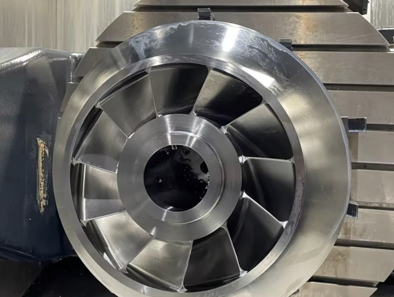
Surface roughness is critical for impeller performance, as it affects fluid flow and efficiency. A surface roughness of Ra 0.8 μm or lower is typically required for blade surfaces to minimize turbulence and cavitation. This is achieved through finishing operations like polishing or grinding, followed by inspection using profilometers. For example, a stainless steel impeller achieved a surface roughness of Ra 0.6 μm after polishing, improving its aerodynamic efficiency by 5%.
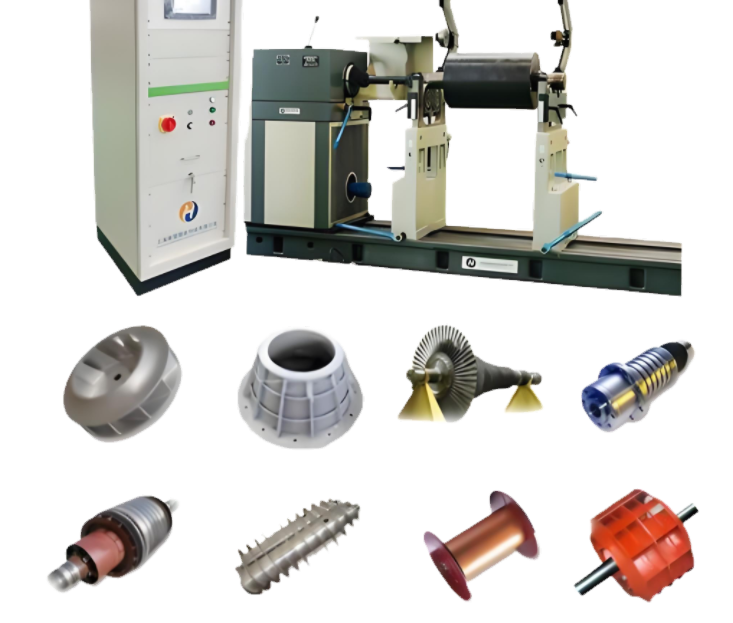
Dynamic balance is essential to prevent vibration during high-speed rotation, typically at speeds up to 14,000 RPM for centrifugal impellers. Balancing machines measure the impeller’s center of mass and apply corrective measures, such as material removal or weight addition, to achieve a balance grade of G2.5 or better, per ISO 1940-1 standards. A 2-inch diameter aluminum impeller was balanced to within 0.01 g-mm, ensuring stable operation in a fuel pump application.
Non-destructive testing (NDT) methods, such as ultrasonic or dye penetrant testing, are used to detect internal defects like cracks or voids. For instance, a titanium impeller underwent ultrasonic testing to confirm the absence of subsurface defects, ensuring structural integrity under high rotational stresses.
| Inspection Parameter | Target Specification | Measurement Tool |
|---|---|---|
| Dimensional Accuracy | ±0.00025 mm | Coordinate Measuring Machine (CMM) |
| Surface Roughness | Ra 0.8 μm | Profilometer |
| Dynamic Balance | G2.5 (ISO 1940-1) | Balancing Machine |