Titanium alloys are critical in aerospace manufacturing due to their high strength-to-weight ratio, corrosion resistance, and ability to withstand extreme conditions. However, their poor machinability poses significant challenges, resulting in surface integrity issues that affect component performance and longevity. This article provides a comprehensive analysis of titanium alloy machining methods, focusing on material characteristics, tool selection, fixture design, cutting parameters, and surface integrity control techniques. The discussion is grounded in practical experience and technical expertise, emphasizing Ti6Al4V, the most widely used titanium alloy in aerospace applications.
Characteristics and Applications of Titanium Alloys
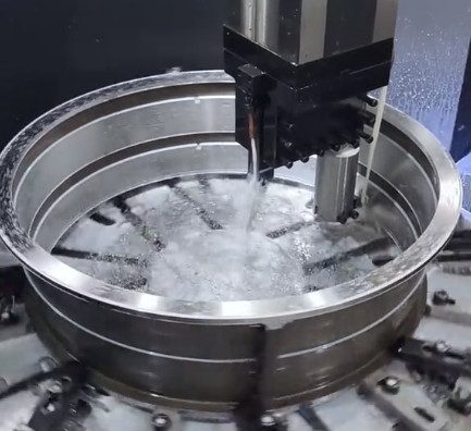
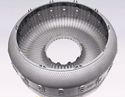
Titanium alloys are extensively utilized in aerospace for components such as engine compressor disks, hollow fan blades, turbine disks, casings, landing gear, outer wing sections, fuselage shells, cabin doors, hydraulic systems, and tail structures. Their usage in aircraft has increased significantly, from 6% to over 15% in modern designs. For instance, the Boeing 777 incorporates 7–9% titanium alloy parts, while the Boeing 787 uses approximately 15% to reduce fuel consumption. In China’s C919 airliner, titanium alloy usage has risen to over 9%, compared to 4.8% in the ARJ21 regional jet.
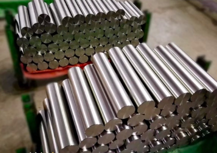
Titanium alloys are classified into α, β, α+β, and titanium-aluminum alloys. The α+β alloy Ti6Al4V is the most prevalent due to its balanced properties, including good toughness, weldability, heat-treatability, and fatigue resistance. Its composition includes titanium (Ti), aluminum (Al), vanadium (V), iron (Fe), oxygen (O), carbon (C), silicon (Si), copper (Cu), and trace amounts of nitrogen (N), hydrogen (H), boron (B), and yttrium (Y). Despite its excellent mechanical properties and low density, Ti6Al4V’s high cutting resistance and low thermal conductivity lead to elevated cutting temperatures, severe tool wear, and work hardening, all of which compromise surface quality and component durability.
Machining Methods for Titanium Alloys
Machining titanium alloys requires careful consideration of tool materials, fixture design, and cutting parameters to mitigate their poor machinability. The following subsections detail these aspects based on established practices.
Tool Selection
Tool materials for titanium alloy machining must exhibit high toughness, thermal hardness, heat dissipation, and wear resistance. Additionally, tools should have sharp cutting edges and smooth surfaces to minimize friction and chip adhesion. Cemented carbide tools with good thermal conductivity and high strength are preferred, typically with small rake angles (0–5°) and larger relief angles (5–10°) to reduce friction and prevent edge chipping. A rounded cutting edge transition is essential to avoid edge fracture.
To prevent affinity reactions between the tool and titanium alloy, titanium-containing carbide tools or coatings are generally avoided, as they accelerate wear through bonding. However, titanium-containing carbides excel in resisting diffusion wear during high-speed cutting compared to YG-grade carbides. Leading tool manufacturers have developed specialized products for titanium alloy machining. For example, ISCAR’s IC20 inserts are suitable for finishing due to their sharp edges, while IC907 inserts offer enhanced wear resistance for roughing and semi-finishing. SECO’s CP200 and CP500 use physical vapor deposition (PVD) for high-hardness, ultra-fine grain structures. Walter’s WSM30, WSM20, and WAM20 employ TiCN, TiAlN, TiN, and Al2O3 coatings for improved deformation and wear resistance.
The reliance on imported tools remains high in aerospace manufacturing, particularly for difficult-to-machine materials like titanium alloys. Developing domestic tool materials and coatings is critical to reducing costs and improving machining efficiency.
Tool Wear and Mitigation Strategies
Titanium alloy machining generates high cutting temperatures and forces, leading to severe tool wear. At high cutting speeds and large depths of cut, a crescent-shaped depression forms on the rake face, reducing edge rigidity and causing chipping. Wear on the flank face creates a zero-relief-angle micro-facet at the cutting edge, exacerbating wear due to work hardening and reduced chip thickness at the secondary cutting edge. Electron microscope images reveal crescent wear, flank wear, and built-up edge (BUE) formation.
BUE can temporarily protect the cutting edge by acting as a substitute edge but negatively impacts surface quality when it detaches irregularly, forming hard spots and burrs. To mitigate BUE, strategies include increasing cutting speed, optimizing depth of cut, using PVD-coated tools, and employing high-pressure cooling systems. Adjusting cutting speed and feed rate based on chip morphology, color, machine load, noise, and vibration helps control rake face wear. Positive rake angle inserts and wear-resistant coatings further extend tool life.
Fixture Design
Titanium alloys are prone to deformation under clamping forces due to their low elasticity. Fixtures must provide sufficient rigidity to withstand high cutting forces while minimizing workpiece distortion. Stable and reliable datum surfaces are critical, with auxiliary supports or over-constrained positioning used when necessary. Clamping forces should be controlled using torque wrenches to avoid excessive pressure, and distributed clamping methods are preferred to prevent localized deformation. Clamping points should be positioned close to the machined surface to reduce vibration.
Fixtures, gauges, and temporary tooling must be free of low-melting-point metals such as lead, zinc, copper, tin, or cadmium to prevent contamination. Equipment and fixtures should be kept clean, and machined titanium parts must be washed promptly to remove residual contaminants. Dedicated storage boxes are used to avoid mixing with other materials, and operators must wear clean gloves during inspection and cleaning to prevent oil or fingerprint contamination, which could lead to salt stress corrosion and compromise service performance.
Cutting Parameters
Cutting parameters—speed, feed rate, and depth of cut—significantly influence titanium alloy machinability. Comparative tests show that constant linear speed cutting outperforms constant rotational speed cutting. Optimal parameters for Ti6Al4V include a cutting speed (vc) of 60 m/min, feed rate (f) of 0.127 mm/rev, and depth of cut (ap) of 0.05–0.1 mm, which minimize surface hardening. Excessive depth of cut in finishing generates excessive heat, altering the surface microstructure and causing hardening, while insufficient depth leads to friction-induced hardening. Feed rates should be moderate, as low feeds accelerate wear in hardened layers, and high feeds increase tool forces, causing deflection or chipping.
| Tool Type | Material/Coating | Cutting Speed (m/min) | Feed Rate (mm/rev) | Depth of Cut (mm) |
|---|---|---|---|---|
| Finishing Insert | IC20 (PVD) | 50–70 | 0.1–0.15 | 0.05–0.1 |
| Roughing Insert | IC907 (PVD) | 30–50 | 0.15–0.3 | 0.5–2.0 |
| General Insert | WSM30 (TiCN/TiAlN) | 40–60 | 0.12–0.2 | 0.1–1.5 |
Cooling Systems
High-pressure cooling systems (60–150 MPa) are essential for titanium alloy machining, increasing cutting speeds by 2–3 times, extending tool life, and improving chip morphology. Cutting fluid reduces cutting forces by 5–15%, radial forces by 10–15%, and temperatures by 5–10%, resulting in better surface morphology with fewer blocky adhesions. Trim E206 emulsion (8% concentrate, 92% water, 7–9% concentration) is effective for turning, milling, and grinding, with additives that control BUE formation. Its fine emulsified particles enhance stability, reduce carry-off, and improve penetration into the cutting zone, while its anti-contamination properties maintain equipment cleanliness.
Surface Integrity Control Techniques
Surface integrity is critical for titanium alloy components, as machining-induced defects such as work hardening, residual stresses, and surface irregularities affect fatigue life and performance. The following subsections outline key inspection and finishing methods.
Microstructural Inspection of Forgings
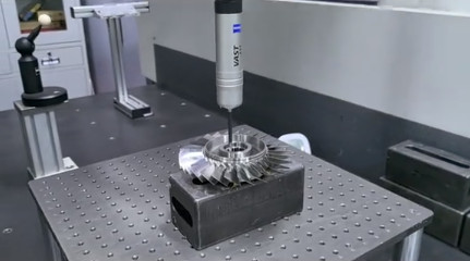
Microstructural inspection evaluates the metallographic structure of titanium alloy forgings to ensure compliance with standards. The process involves rough machining to remove the α-layer, polishing with 400–800# aluminum oxide sandpaper to achieve a surface roughness of Ra 0.025 μm or better, etching with Kroll’s reagent (2% HF, 4% HNO3, water), rinsing, drying, and examining with a handheld electron microscope. Qualified Ti6Al4V structures contain 10–50% primary α-phase, with acceptable morphologies including primary α in a β-transformed matrix, discontinuous α at β grain boundaries, or lamellar α in β grains.
Blue Anodization Corrosion Testing
Blue anodization detects machining-induced work hardening by revealing surface defects through color changes. After anodization, a uniform light blue oxide film indicates a defect-free surface, while deep blue or localized dark areas signal work hardening due to excessive tool flank wear or overheating. Corrective measures include optimizing tool materials, coatings, cutting angles, tool paths, and parameters to eliminate hardening.
Surface Finishing
Manual butterfly finishing removes surface defects from components like compressor disks, hubs, impellers, shafts, and rotor spacers, enhancing service life. Tools include a rotary air gun (18,000 rpm), polishing rod, and 120# aluminum oxide or silicon carbide sandpaper (10 mm × 20 mm). Sandpaper is folded, inserted into the polishing rod’s slot, and secured opposite the rotation direction. Finishing involves 1–2 cycles of reciprocating motion (10–30 s per cycle, 1.57 mm/s), with sandpaper replaced between cycles. A torque wrench or mechanical depth stop controls penetration to ensure consistency.
Conclusion
Titanium alloy machining requires careful selection of tools, fixtures, and cutting parameters to address high cutting forces, elevated temperatures, and severe tool wear. Cemented carbide tools with optimized geometries and coatings, rigid fixture designs, and precise cutting parameters (e.g., vc = 60 m/min, f = 0.127 mm/rev, ap = 0.05–0.1 mm) improve efficiency and surface quality. High-pressure cooling systems and specialized cutting fluids like Trim E206 enhance performance. Surface integrity is maintained through microstructural inspection, blue anodization testing, and butterfly finishing, ensuring defect-free components with extended service life. These methods, grounded in practical experience, provide a systematic approach to achieving high-quality titanium alloy parts in aerospace manufacturing.