CNC (Computer Numerical Control) machining is a cornerstone of modern manufacturing, enabling the production of highly precise parts through automated control of multi-axis machines. Tolerance control is critical in axis processing to ensure that components meet exact dimensional specifications, fit seamlessly in assemblies, and perform reliably in their intended applications. This guide provides a detailed, technical exploration of tolerance control techniques in CNC axis processing, focusing on practical methods, key parameters, and best practices to achieve high precision. The content is structured to offer clear, systematic insights for engineers, machinists, and manufacturers seeking to optimize their processes.
Understanding Tolerances in CNC Axis Processing
Tolerance in CNC machining refers to the permissible range of dimensional variation in a machined part that still allows it to function as intended. In axis processing, which involves multi-axis CNC machines (typically 3-axis, 4-axis, or 5-axis systems), tolerances dictate how closely the machined part must adhere to the design specifications. Tolerances are expressed as bilateral (±0.1 mm), unilateral (+0.1/-0 mm), or limit tolerances (e.g., 10.1 mm to 9.9 mm). Standard tolerances for CNC machining typically range from ±0.05 mm to ±0.13 mm, depending on the material, machine, and process. For high-precision applications, such as aerospace or medical components, tolerances can be as tight as ±0.005 mm.
Achieving tight tolerances in axis processing requires a deep understanding of machine capabilities, material properties, and environmental factors. Multi-axis machines, particularly 5-axis systems, allow for complex geometries by enabling simultaneous movement in multiple directions (X, Y, Z, and rotational axes A, B, or C). However, this complexity introduces challenges in maintaining consistent tolerances across all axes. The following sections outline key techniques to control tolerances effectively in CNC axis processing.
Machine Calibration and Setup for Precision
Proper machine calibration and setup are foundational to achieving tight tolerances in CNC axis processing. Calibration ensures that the machine's axes are aligned, and the tool paths are accurate. Misalignment in any axis can lead to cumulative errors, resulting in parts that fall outside specified tolerances.
Axis Alignment and Homing: Multi-axis CNC machines require precise homing or zeroing to establish a reference point for all movements. This process involves manually or automatically setting the machine to a known position using absolute position sensors, such as optical encoders. For example, a 5-axis machine must align its X, Y, Z, A, and B axes to ensure that tool paths are executed accurately. Regular calibration checks, typically performed daily or per shift, help maintain alignment.
Tool Path Optimization: The tool path, generated by CAM (Computer-Aided Manufacturing) software, must account for the machine's kinematic capabilities. For instance, in 5-axis machining, the tool path should minimize abrupt changes in direction to reduce vibration and maintain dimensional accuracy. Parameters such as feed rate (typically 50-200 mm/min for steel) and spindle speed (10,000-20,000 RPM for high-speed machining) must be optimized based on material and tool type.
Fixture Design: Workholding fixtures must securely hold the workpiece without introducing stress or deformation. For complex parts machined on 5-axis systems, custom fixtures with multiple clamping points are often used to ensure stability. Fixture tolerances should be at least half that of the part (e.g., ±0.025 mm for a part tolerance of ±0.05 mm) to avoid compounding errors.
Tool Selection and Maintenance
The choice and condition of cutting tools significantly impact tolerance control in CNC axis processing. Tools must be selected based on material properties, geometry requirements, and machining conditions.
Tool Material and Geometry: For hard materials like stainless steel or titanium, carbide tools with coatings such as TiAlN (Titanium Aluminum Nitride) are preferred due to their durability and heat resistance. Tool geometry, including rake angle (typically 5-15°) and helix angle (30-45° for milling), affects chip evacuation and surface finish, which directly influence dimensional accuracy.
Tool Wear Monitoring: Tool wear is a primary cause of dimensional drift. As a tool wears, its cutting edge dulls, leading to increased cutting forces and potential deviations from specified tolerances. Advanced CNC machines incorporate tool wear monitoring systems that measure parameters like spindle load or vibration. For example, a 10% increase in spindle load may indicate the need for tool replacement. Regular inspections, typically after 50-100 machining cycles, help maintain consistency.
Tool Path Compensation: CAM software can adjust tool paths to compensate for known tool wear. For instance, if a tool's diameter reduces by 0.01 mm due to wear, the software can offset the path to maintain the desired dimension. This is particularly critical in 5-axis machining, where tool orientation changes frequently.
Material Considerations for Tolerance Control
Material properties significantly affect achievable tolerances in CNC axis processing. Different materials respond uniquely to machining forces, thermal effects, and tool interactions.
Material Hardness and Ductility: Hard materials like tool steel (Rockwell C 40-60) allow for tighter tolerances due to their stability during machining. Softer materials, such as aluminum (Rockwell B 60-80) or plastics, may deform under cutting forces, making tolerances of ±0.05 mm or tighter challenging. For example, machining ABS plastic may require slower feed rates (20-50 mm/min) to minimize deformation.
Thermal Expansion: Temperature changes during machining can cause materials to expand or contract, affecting dimensions. For instance, aluminum has a thermal expansion coefficient of 23.6 µm/m·°C, meaning a 10°C temperature increase can cause a 0.0236 mm expansion per meter. Advanced CNC systems use thermal compensation systems with real-time temperature sensors to adjust tool paths dynamically, maintaining tolerances as tight as ±0.005 mm.
Material Consistency: Variations in material composition, such as inclusions or porosity, can lead to inconsistent machining results. Using certified materials with known properties (e.g., 316 stainless steel with consistent grain structure) ensures predictable machining behavior.
Advanced Techniques for Tight Tolerances
Achieving ultra-tight tolerances (e.g., ±0.01 mm or less) in axis processing requires advanced techniques that go beyond standard practices.
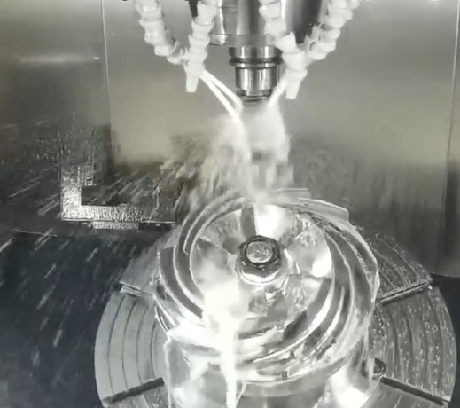
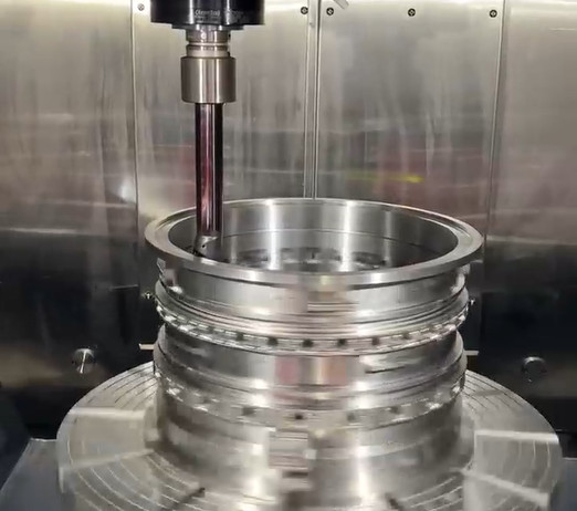
High-Precision Machining Centers: 5-axis CNC machines with high-resolution linear encoders and closed-loop control systems can achieve tolerances as low as ±0.005 mm. These machines use servo motors and feedback systems to correct positional errors in real time. For example, a high-precision 5-axis mill may have a positional accuracy of 0.002 mm per axis.
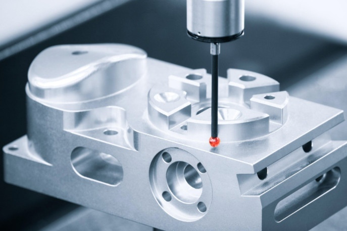
In-Process Monitoring: Real-time monitoring systems, such as laser probes or touch probes, measure part dimensions during machining. If a deviation is detected, the system adjusts the tool path or halts the process. For instance, a touch probe with 0.001 mm resolution can verify critical features like hole diameters mid-process.
Post-Processing Considerations: Post-machining processes like heat treatment or plating can alter dimensions. For example, heat treatment may cause a steel part to shrink by 0.01-0.02 mm. To account for this, initial tolerances may be set looser (e.g., ±0.03 mm) to allow for final finishing to achieve ±0.01 mm.
Quality Control and Inspection
Robust quality control (QC) processes are essential to verify that tolerances are met in CNC axis processing. Inspection methods must match the precision of the machining process.
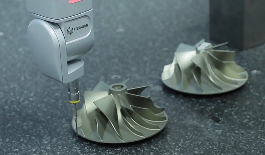
Coordinate Measuring Machines (CMMs): CMMs use probes to measure part dimensions with accuracies of ±0.001 mm. They are ideal for verifying complex geometries produced by 5-axis machines. For example, a turbine blade with a tolerance of ±0.01 mm may require CMM inspection to ensure profile accuracy.
Gauges and Calipers: For less critical features, digital calipers (0.01 mm resolution) or height gauges can verify dimensions. These are cost-effective for standard tolerances of ±0.05 mm or higher.
Statistical Process Control (SPC): SPC involves collecting dimensional data from multiple parts to monitor process stability. For instance, a control chart tracking a shaft diameter may show a mean of 25.00 mm with a standard deviation of 0.02 mm, indicating a stable process within ±0.05 mm tolerance.
| Inspection Method | Accuracy | Application |
|---|---|---|
| Coordinate Measuring Machine (CMM) | ±0.001 mm | Complex geometries, tight tolerances |
| Digital Caliper | ±0.01 mm | Standard tolerances, linear dimensions |
| Laser Probe | ±0.002 mm | In-process verification |
Optimizing Tolerances for Cost and Efficiency
Balancing tolerance requirements with cost and efficiency is critical in CNC axis processing. Tighter tolerances increase machining time, tool wear, and inspection costs, while looser tolerances may compromise part functionality.
Selective Tolerancing: Specify tight tolerances (e.g., ±0.01 mm) only for critical features, such as mating surfaces or bearing seats, while using standard tolerances (e.g., ±0.13 mm) for non-critical areas. This approach reduces production costs by 15-30% compared to uniformly tight tolerances.
Process Capability Analysis: Evaluate the machine’s capability (Cp and Cpk indices) to determine achievable tolerances. A Cpk of 1.33 or higher indicates a process capable of consistently meeting tolerances. For example, a 5-axis mill with a Cpk of 1.5 can reliably produce parts within ±0.05 mm.
Simulation and Validation: Use machining simulation software to predict dimensional outcomes before cutting. Modern CAM systems model the entire machine tool envelope, including axes, spindles, and fixtures, to identify potential tolerance issues. Simulations can reduce scrap rates by up to 20%.
Practical Applications in Axis Processing
Tolerance control techniques are applied across industries, with specific requirements varying by application.
Aerospace: Turbine blades require tolerances of ±0.001 mm to withstand high temperatures and stresses. 5-axis CNC machines with thermal compensation systems are used to achieve these tolerances.
Automotive: Engine components like crankshafts demand tolerances of ±0.01 mm for precise fit and performance. Multi-axis machining ensures consistent dimensions across complex geometries.
Medical: Surgical implants require tolerances of ±0.005 mm to ensure biocompatibility and functionality. High-precision 5-axis machines with in-process monitoring are critical.
| Industry | Typical Tolerance | Key Application |
|---|---|---|
| Aerospace | ±0.001 mm | Turbine blades |
| Automotive | ±0.01 mm | Crankshafts |
| Medical | ±0.005 mm | Surgical implants |
Conclusion
Tolerance control in CNC axis processing is a multifaceted discipline that requires meticulous attention to machine setup, tool selection, material properties, and quality control. By implementing techniques such as precise calibration, tool wear monitoring, thermal compensation, and selective tolerancing, manufacturers can achieve the desired precision while optimizing cost and efficiency. The use of advanced 5-axis machines, real-time monitoring, and robust inspection methods further enhances the ability to meet stringent tolerances. This guide provides a systematic framework for professionals to refine their CNC machining processes, ensuring high-quality, reliable parts for demanding applications.