
An impeller is a rotating component used in pumps and compressors to transfer energy from a motor to a fluid, increasing its pressure and flow rate. It is a critical element in centrifugal pumps, compressors, and other turbomachinery, converting mechanical energy into fluid kinetic energy. Impellers are designed to optimize fluid dynamics, enhance efficiency, and ensure durability under various operating conditions. This article provides a detailed overview of impellers, their types, key design parameters, and applications, supported by technical data and structured for clarity.
Definition of an Impeller
An impeller is a rotor that accelerates fluid outward from its center of rotation, generating pressure and flow within a pump or compressor. Unlike a turbine, which extracts energy from a fluid, an impeller imparts energy to it. Typically, impellers feature vanes arranged around a central shaft, with fluid entering axially through an inlet (called the "eye") and exiting radially or axially, depending on the design. Impellers are integral to devices like centrifugal pumps, agitation tanks, and compressors, where they facilitate fluid movement in specific directions. For demanding environments, impellers are fabricated from high-difficulty materials such as titanium alloys, superalloys (e.g., Inconel), or advanced composites, selected for their exceptional strength, corrosion resistance, and ability to withstand extreme temperatures and aggressive fluids.
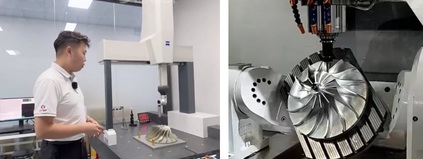
Manufacturing involves high-difficulty processes like precision investment casting, multi-axis CNC machining, or additive manufacturing (3D printing) to achieve complex geometries with tight tolerances. High-difficulty surface treatments, such as plasma-sprayed ceramic coatings, diamond-like carbon (DLC) coatings, or nitriding, enhance durability, reduce friction, and resist wear under harsh conditions. Dynamic balancing is performed using advanced laser-guided systems to eliminate micro-vibrations, ensuring stable operation at high speeds. High-difficulty precision testing employs techniques like coordinate measuring machines (CMM), X-ray computed tomography, and interferometric surface analysis to verify sub-micron tolerances and internal integrity, guaranteeing optimal performance and reliability in critical applications.
Types of Impellers
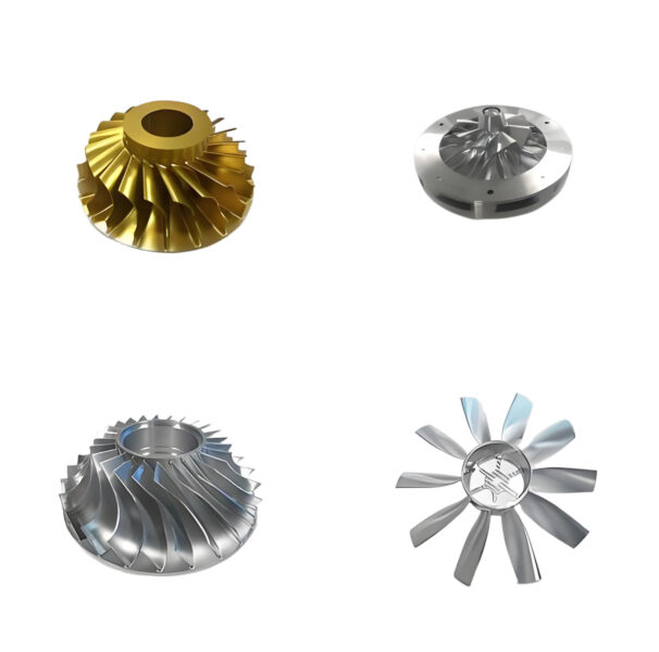
Impellers are classified based on their design and flow characteristics. The main types include open, semi-open, closed, and specialized designs like vortex and cutter impellers. Each type is suited to specific applications, balancing efficiency, strength, and solid-handling capabilities.
| Impeller Type | Description | Applications | Advantages | Disadvantages |
|---|---|---|---|---|
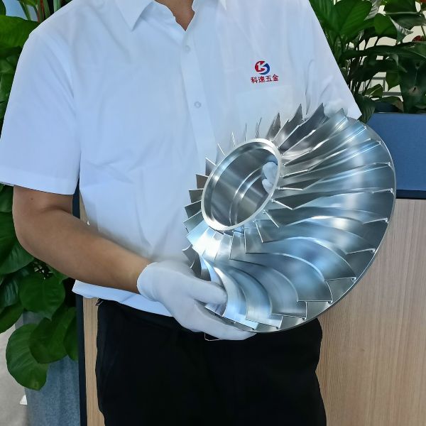
| Open | Vanes attached to a hub without shrouds, open on both sides. | Small pumps, handling suspended solids. | Easy to inspect, maintain, and modify; suitable for solids. | Lower strength, higher NPSH required, less efficient. |
| Semi-Open | Vanes with a back shroud, open on the inlet side. | Medium-sized pumps with small amounts of soft solids. | Improved strength over open impellers, moderate efficiency. | Requires tight vane-casing clearance, moderate solid handling. |
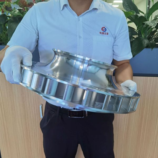
| Closed | Vanes enclosed by shrouds on both sides. | Large pumps for clean liquids. | High efficiency, low NPSH, strong structure. | Complex design, higher maintenance due to wear rings. |
| Vortex | Non-channel impeller creating a whirlpool effect. | Dirty fluids with debris or stringy solids. | Excellent solid handling, low clogging risk. | Lower efficiency, not ideal for clean liquids. |
| Cutter | Sharp-edged vanes to grind solids before pumping. | Sewage, wastewater with solids. | Handles tough solids by cutting them. | Lower efficiency, specialized use. |
Key Design Parameters
Impeller performance depends on several geometric and operational parameters. These factors influence head, flow rate, efficiency, and durability. The following table summarizes critical parameters and their impact.
| Parameter | Description | Impact on Performance |
|---|---|---|
| Impeller Diameter | Size of the impeller, affecting head and flow rate. | Larger diameters increase head and flow but raise energy consumption (H ∝ D²). |
| Blade Angle | Inlet (β₁) and outlet (β₂) angles of vanes. | Optimized angles reduce turbulence and enhance energy transfer efficiency. |
| Number of Blades | Total count of vanes on the impeller. | More blades improve efficiency but increase manufacturing complexity. |
| Blade Shape | Curvature and profile of vanes (e.g., radial, axial, mixed). | Curved blades reduce turbulence, improving efficiency for specific flow types or turbine rotor impellers. |
| Impeller Width | Width of the impeller prototype affecting flow capacity. | Wider impellers handle higher flow rates but may increase friction losses. |
| Material | Construction material (e.g., stainless steel, bronze, plastic). | Affects durability, corrosion resistance, and suitability for specific fluids. |
| Surface Finish | Smoothness of impeller surfaces. | Smoother finishes reduce friction and turbulence, enhancing efficiency. |
| Rotation Speed | Speed of impeller rotation (RPM). | Higher speeds increase flow and pressure but may cause cavitation or wear. |
Operational Characteristics
Impellers operate by accelerating fluid outward, creating a pressure differential that drives flow. Key operational aspects include:
- Flow Coefficient: Describes volumetric flow as a function of tip diameter and speed. Lower coefficients suit 2D shrouded impellers, while higher coefficients require 3D or axial-flow designs.
- Pressure Pulsation: At high rotation speeds (e.g., 45,000 RPM), blade passing frequency (BPF) generates noise signals, with dominant frequencies like 5.25 kHz (half BPF) and 10.5 kHz (BPF).
- Efficiency: Efficiency increases with flow coefficient but may decrease with wider impellers due to friction losses. Closed impellers typically offer higher efficiency than open designs.
- Cavitation: High-speed impellers risk cavitation, requiring careful inlet sizing and net positive suction head (NPSH) calculations to prevent performance degradation.
Applications of Impellers
Impellers are used across industries for fluid movement and pressure generation. Common applications include:
- Centrifugal Pumps: Used in water supply, wastewater treatment, and oil and gas industries to move liquids.
- Compressors: Employed in HVAC systems, refrigeration, and industrial gas processing.
- Agitation Tanks: Facilitate mixing in chemical processing, bioreactors, and fermentation tanks.
- Turbomolecular Pumps: Used in high-vacuum systems, such as semiconductor manufacturing and scientific research, to achieve ultra-low pressures by accelerating gas molecules toward exhaust stages.
- Washing Machines: Drive water movement for cleaning cycles.
- Specialized Systems: Vortex impellers handle sewage, while cutter impellers process solid-laden wastewater.

Impeller Design, Simulation, and Manufacturing
Modern impeller design utilizes computational fluid dynamics (CFD) and computer-aided design (CAD) tools like ANSYS CFX, FLUENT, SolidWorks, BLADEGEN, and TURBOGRID to optimize performance. These tools enable simulation of fluid flow, pressure, and cavitation; precise geometry modeling with accurate meshing; stress and deformation analysis; and optimization of blade parameters (angle, number, diameter). This streamlines design, enhances accuracy, and supports virtual prototyping, reducing costly physical iterations.
Manufacturing: Impeller production requires high-precision methods to achieve complex geometries. CNC machining ensures accurate shaping, investment casting supports intricate designs, and additive manufacturing (3D printing) enables rapid prototyping and specialized alloys. Tight tolerances and smooth surface finishes are essential for hydraulic efficiency and durability. Post-processing, like polishing or applying wear- and corrosion-resistant coatings, enhances longevity. Quality control includes dimensional inspections, non-destructive testing, and performance validation to meet design specifications. Materials such as aluminum, stainless steel, titanium, or composites are chosen to withstand operational stresses, abrasive slurries, or corrosive fluids in impeller machining.
Key Issues:
- Design: Optimizing blade geometry and flow paths is complex, as improper configurations can lead to turbulence or reduced efficiency.
- Simulation: Accurately predicting cavitation and stress under varying conditions requires sophisticated models and computational resources.
- Manufacturing: Fabricating closed impellers with precise tolerances is challenging and costly in manufacturing complexity, often requiring advanced mult-axis techniques and rigorous high quality control.
- Performance: Cavitation from high-speed rotation forms vapor bubbles, reducing efficiency and damaging surfaces. Abrasive particles in slurry pumps cause wear, necessitating durable materials and coatings.
Conclusion
Impellers are essential components in fluid-handling systems, with their performance governed by design parameters like diameter, blade angle, and material selection. By understanding impeller types, operational characteristics, and design challenges, engineers can optimize efficiency and durability for specific applications. CFD and CAD tools further enhance design precision, making impellers critical to industries ranging from water management to chemical processing.